Sony NSR-50 handleiding
Handleiding
Je bekijkt pagina 27 van 200
I/O Port
27
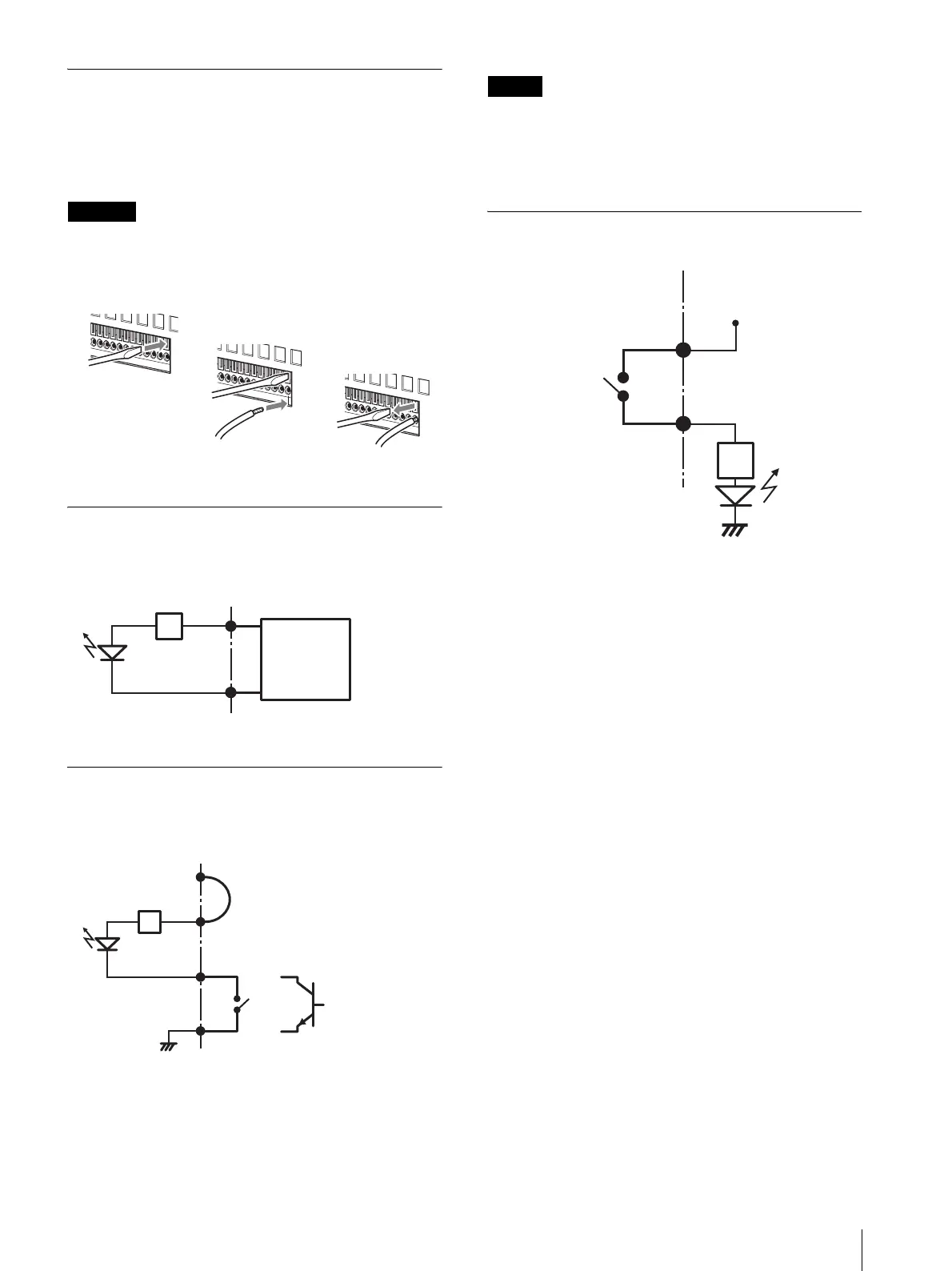
Using the I/O Receptacle
Insert a small slotted screwdriver into the upper or lower
slot of the hole you want to connect a wire to (AWG No.
28 to 18). Hold down the screwdriver and insert the wire,
then release the screwdriver.
Caution
Do not use excessive force when inserting the
screwdriver into the slot. Doing so may result in
damage.
Repeat this procedure to connect all required wires.
Wiring Diagram 1 for Sensor Input
Wiring Diagram 2 for Sensor Input
Note
When the wiring diagram 2 is used, the NSR is not
electrically isolated, so be sure to construct external
circuits that will not produce noise, excess voltage, or
overcurrents.
Wiring Diagram for Alarm Output
1
2
3
3, 5, 7, 9, 11, 13, 15, 17pin
(SENSOR IN+)
2, 4, 6, 8, 10, 12, 14, 16pin
(SENSOR IN-)
2.35 kΩ
Sensor
device
Output:
3.3 to 24 V
DC
Inside of this unit Outside
3, 5, 7, 9, 11, 13, 15,
17pin
(SENSOR IN+)
2, 4, 6, 8, 10, 12, 14,
16pin
(SENSOR IN-)
2.35 kΩ
Wire
Inside of this unit Outside
1 pin (VDD) (200 mA max)
Mechanical
switch
18pin (GND)
GND
or
Open collector
output device
3, 5, 7, 9, 11, 13,
15, 17pin
(ALARM OUT+)
2, 4, 6, 8, 10, 12,
14, 16pin
(ALARM OUT-)
Magnet relay
24 V AC/24 V DC,
1 A or less
Inside of this unit Outside
5 V
Circuit example
GND
Bekijk gratis de handleiding van Sony NSR-50, stel vragen en lees de antwoorden op veelvoorkomende problemen, of gebruik onze assistent om sneller informatie in de handleiding te vinden of uitleg te krijgen over specifieke functies.
Productinformatie
| Merk | Sony |
| Model | NSR-50 |
| Categorie | Niet gecategoriseerd |
| Taal | Nederlands |
| Grootte | 41738 MB |
Caratteristiche Prodotto
| Gewicht | 12000 g |
| Stroomvoorziening | 100 - 127, 200 - 240 V AC |
| Framerate Motion JPEG | 240 fps |
| Aansluitingen | 2 x RGB\n2 x Mini jack\n2 x RCA-pin\n3 x RJ-45\n4 x USB\n1 x RS-232C (UPS) |
| Compatibele besturingssystemen | Linux |


