Sommer ASB-6010A handleiding
Handleiding
Je bekijkt pagina 15 van 61
15
Installation preparations
Observe the following information for the preparation
of installation:
RISK OF CRUSH INJURIES TO HANDS!
Risk of crushing at the lever system of the barrier when
the hood is open.
¾ All work on the barrier must be carried out by qualied
personnel!
¾ Before working on the barrier, always disconnect
the system and secure it to prevent reactivation!
¾ Install the barrier housing without the boom!
¾ Follow the instructions on personal protective
equipment!
¾ The total length of the boom is not equal to the eective opening width.
¾ For a boom length of more than 4 metres, a oating support or
support post is required. There must be a safety distance of at least
500 mm (A) in each case between the barrier housing/the tip of the
boom and the next stationary obstacle (building, wall, fence, etc.).
¾ The mains connection must be in accordance with EN 12453 (all-pole
mains circuit breaker). For this purpose, install a lockable main switch
(all-pole deactivation).
¾ Operate barriers only with a permanently laid line protected by a fuse
(16A, slow-acting). The power cord connected in the as-delivered state
is not approved for constant or outdoor operation.
¾ A minimum distance of 5 metres must be observed between the
range of movement of the barrier and overhead power lines/trees.
¾ Provide empty ducts in the foundation of the barrier and throughout
the installation site for the cables of the mains supply line and the
accessories (photocell, warning light, key switch, etc.).
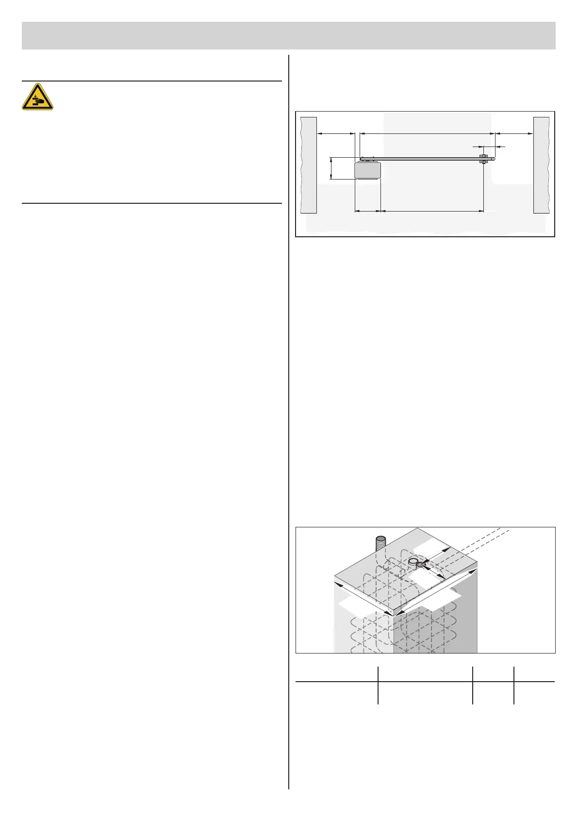
Installation drawing
The position of the foundation, the length of the boom, and, where
applicable, the position of the support post can be calculated using the
overview illustration.
Y
≥ 500
300
≥ 500X
350 Z = X - 280 - Y
AA
X = Boom length (1500 mm to 6000 mm)
Y = Distance from the tip of the boom to the centre of the support post or
oating support. Minimum 150 mm, maximum 300 mm
Z = Opening width of the barrier - drive-through width
Example calculation:
Calculation of the boom length (X) with:
Opening width of the barrier (Z) = 3500 mm
Distance between the tip of the boom and the centre of the support post (Y)
= 200 mm
X = Z + Y + 280 mm
X = 3500 mm + 200 mm + 280 mm
X = 3980 mm
Creating the barrier foundation
with supply connections
For the proper operation of the barrier, the barrier housing must stand
securely.
The following table shows the foundation size recommended by
SOMMER Antriebs- und Funktechnik GmbH. Depending on the danger
of frost, the depth of the foundation (D) must be adapted in a frost-proof
manner so that the ground cannot lift.
150
400
150
300
D W L
Recommended Frost-proof!
800 mm in Germany
300 mm 400 mm
Bekijk gratis de handleiding van Sommer ASB-6010A, stel vragen en lees de antwoorden op veelvoorkomende problemen, of gebruik onze assistent om sneller informatie in de handleiding te vinden of uitleg te krijgen over specifieke functies.
Productinformatie
| Merk | Sommer |
| Model | ASB-6010A |
| Categorie | Niet gecategoriseerd |
| Taal | Nederlands |
| Grootte | 7965 MB |

