Sime Murelle 70 Box ErP handleiding
Handleiding
Je bekijkt pagina 6 van 56
6
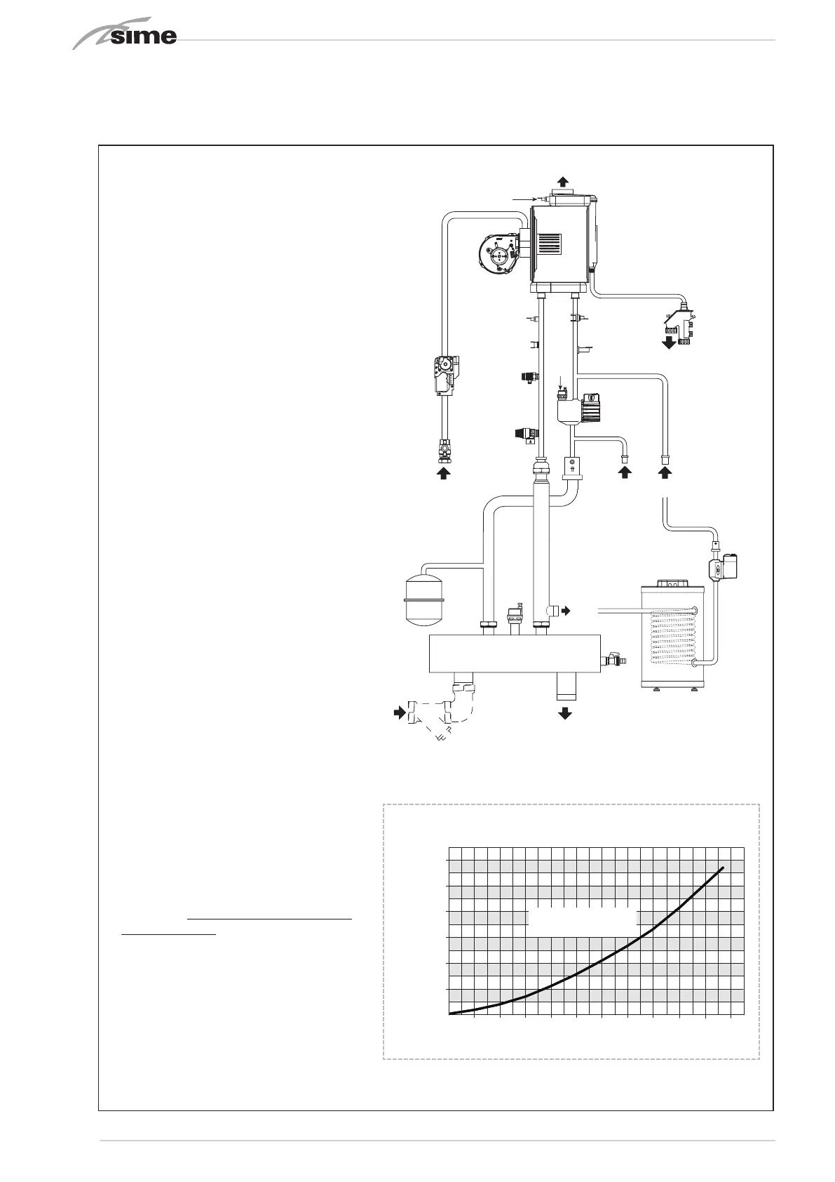
1.4 OPERATING DIAGRAM (fig. 2)
SOLUZIONE PER EXPORT SOLUZIONE PER ITALIA
20
M
M2
18
3
29
19
23
R
8
4
7
5
6
10
11
2
13
14
17
12
1
15
21
25
30
22
24
27
28
26
16
C
R3
G
S3
20
M
M2
18
3
29
19
23
R
8
4
7
5
6
10
11
2
13
14
17
12
1
15
21
22
16
C
R3
G
S3
KEY
1 Gas valve
2 Condensate drain siphon
3 Boiler pump (not supplied)
4 Fan
5 Heating supply probe (SM)
6 100°C Safety thermostat
7 Flue gas probe (SF)
8 Primary exchanger
10 Heating return probe (SR)
11 Water pressure transducer
12 Automatic vent
13 High efficiency system pump
14 Boiler exhaust
15 Gas tap (not supplied)
16 Check valve
17 3.5 bar safety valve
18 Check valve (not supplied)
19 Hydraulic compensator
20 Drain cock
21 8 litre expansion vessel
22 Automatic vent
23 Y strainer (not supplied)
29 D.H.W. tank (not supplied)
CONNECTIONS
M System supply
R System return
G Gas
S3 Condensate drain
C System filling
M2 D.H.W. tank supply
R3 D.H.W. tank return
600
1000
4500
400035003000250020001500
PORTATA (l/h)
PERDITE DI CARICO TRA
GLI AT TACCHI R3 e M2 (mbar)
500
400
100
200
300
700
800
5000
5500
Murelle HE 92.5 R ErP
Murelle HE 110 R ErP
600
200
1600
140012001000800600400
PORTATA (l/h)
PERDITE DI CARICO TRA
GLI AT TA CCHI R3 e M2 (mbar)
500
400
100
200
300
Murelle HE 50 R ErP
Murelle HE 70 R ErP
2200
20001800
600
200
1600
140012001000800600400
PORTATA (l/h)
PERDITE DI CARICO TRA
GLI AT TA CCHI R3 e M2 (mbar)
500
400
100
200
300
700
800
Murelle HE 35 R ErP
PRESSURE/FLOW DROPS CURVE
BETWEEN R3 and M2 CONNECTIONS
WARNING:
The boiler pump (3) to be used must be
sized according to the DHW circuit drops
(boiler + piping) and minimum flow rate, in
order to guarantee (2,200 l/h).
The boiler (29) shall be controlled through
the RVS control unit (configure the instal-
ler parameter PAR 10).
Only if the Murelle 70 BOX ErP is to be
installed indoors when the boiler (29) is
connected will it be necessary to:
- configure the installer parameter PAR
2=6.
- electrically connect the boiler pump (3)
to terminal 18-20 of connector CN9 on
the boiler board.
- move the capillary from the siphon anti-
freeze probe (2) to the boiler so that it
acts as a boiler probe.
Fig. 2
PRESSURE DROP BETWEEN
THE R3 M2 CONNECTIONS (mbar)
FLOW RATE (l/h)
MURELLE 70 BOX ErP
Bekijk gratis de handleiding van Sime Murelle 70 Box ErP, stel vragen en lees de antwoorden op veelvoorkomende problemen, of gebruik onze assistent om sneller informatie in de handleiding te vinden of uitleg te krijgen over specifieke functies.
Productinformatie
| Merk | Sime |
| Model | Murelle 70 Box ErP |
| Categorie | Niet gecategoriseerd |
| Taal | Nederlands |
| Grootte | 8576 MB |


