Sime Murelle 70 Box ErP handleiding
Handleiding
Je bekijkt pagina 25 van 56
25
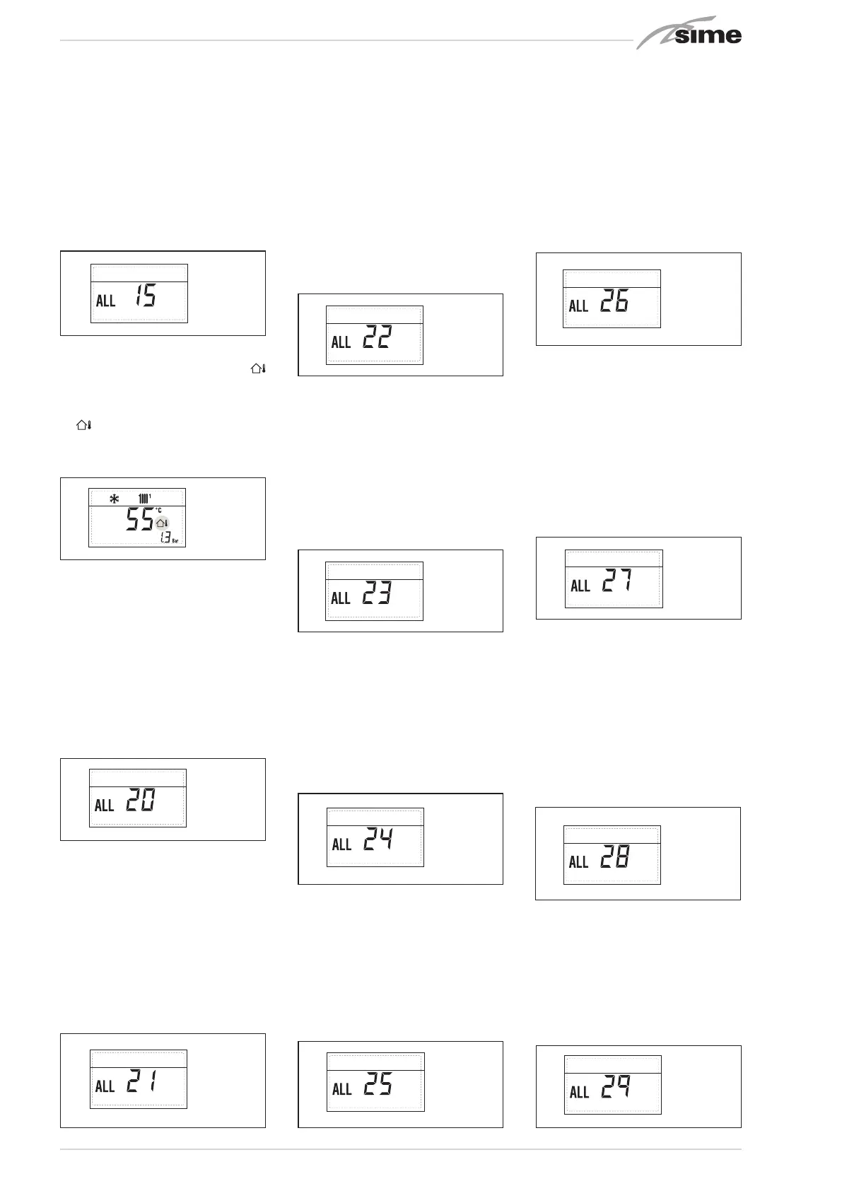
– “ALL 15” FAN ERROR (fig. 23/12)
The fan speed does not fall within the
rated speed range.
If the error conditions persists for two
minutes, the generator activates a
forced stop for thirty minutes.
A new start attempt is repeated after the
expiry of this interval of time.
– EXTERNAL PROBE ERROR “
5
3
1
2
4
FLASHING” (fig. 23/13)
When the external probe (SE) is short-
circuited, the display the symbol flashes
5
3
1
2
4
.
During such error the boiler continues
normal functioning.
– SAFETY THERMOSTAT INTERVENTION
FIRST MIXED ZONE “ALL 20” (fig. 23/14)
When it results that the MIXED ZONE
board is connected to the boiler the
safety thermostat intervention switch-
es the mixed zone plant pump, the mix
zone valve closes and on the display the
anomaly ALL 20.
During this anomaly the generator con-
tinues to function normally.
– DELIVERY PROBE BREAKDOWN ANOM-
ALY FIRST MIXED ZONE “ALL 21” (fig.
23/15)
When it results that the MIXED ZONE
board is connected to the boiler and the
delivery probe is open or short circuit-
ed on the display the anomaly ALL 21
appears.
During this anomaly, the boiler contin-
ues to function normally.
– SAFETY THERMOSTAT INTERVENTION
SECOND MIXED ZONE “ALL 22” (fig.
23/16)
When it results that the MIXED ZONE
board is connected to the boiler
The intervention of the safety thermostat
switches the mixed zone plant pump,
the mix zone valve closes and on the
display the anomaly ALL 22. During this
anomaly the boiler continues to function
normally.
– DELIVERY PROBE BREAKDOWN ANOM-
ALY SECOND MIXED ZONE “ALL 23” (fig.
23/17)
When it results that the MIXED ZONE
board is connected to the boiler and the
delivery probe is open or short circuit-
ed on the display the anomaly ALL 23
appears. During this anomaly the boiler
continues to function normally.
– SOLAR COLLECTOR SENSOR ANOMALY
S1 “ALL 24” fig. 23/18)
When the solar probe is open or short
circuited, on the display the anomaly
ALL 24 appears. During this anomaly the
boiler continues to function normally but
loses the solar function that is no longer
available.
– SOLAR PROBE ANOMALY STORAGE
TANK S2 “ALL 25” fig. 23/19)
When the solar probe is open or short
circuited, on the display the anomaly
ALL 25 appears. During this anomaly the
boiler continues to function normally but
loses the solar function that is no longer
available.
– AUXILIARY SENSOR ANOMALY S3
“ALL 26” fig. 23/20)
When the solar probe is open or short
circuited, on the display the anomaly
ALL 26 appears. During this anomaly the
boiler continues to function normally but
loses the solar function that is no longer
available.
– ANOMALY SOLAR APPLICATION COM
PATIBILITY “ALL 27” fig. 23/21)
When the hydraulic configuration is
not consistent with the selection solar
application, on the display the anomaly
ALL 27 appears. During this anomaly
the boiler continues to function normally
but for the board is active in the solar
anomaly, the function is only available
antifreeze collector.
– COMPATIBILITY INPUT S3 ANOMA-
LY ONLY FOR SYSTEM 7 “ALL 28” fig.
23/22)
When a probe is connected instead of a
clean contact on entry S3 the board on
display shows the anomaly ALL 28. Dur-
ing this anomaly the boiler continues to
function normally but for the board is
active in the solar anomaly, the function
is only available antifreeze collector.
– ANOMALY NUMBERS RELATED BOARD
“ALL 29” (fig. 23/23)
When one of the board MIXED ZONE/
INSOL failure or does not communicate,
the display shows anomaly ALL 29. The
boiler functional excluding the function
MIXED ZONE/SOLAR.
Apre
2
2
2
Circuito
riscaldamento 2
Circuito
riscaldamento 3
(impianto tre
zone)
Fig. 23/12
Apre
2
2
2
Circuito
riscaldamento 2
Circuito
riscaldamento 3
(impianto tre
zone)
Fig. 23/13
Apre
2
2
2
Circuito
riscaldamento 2
Circuito
riscaldamento 3
(impianto tre
zone)
Fig. 23/14
Apre
2
2
2
Circuito
riscaldamento 2
Circuito
riscaldamento 3
(impianto tre
zone)
Fig. 23/15
Apre
2
2
2
Circuito
riscaldamento 2
Circuito
riscaldamento 3
(impianto tre
zone)
Fig. 23/16
Apre
2
2
2
Circuito
riscaldamento 2
Circuito
riscaldamento 3
(impianto tre
zone)
Fig. 23/17
Apre
2
2
2
Circuito
riscaldamento 2
Circuito
riscaldamento 3
(impianto tre
zone)
Fig. 23/23
Apre
2
2
2
Circuito
riscaldamento 2
Circuito
riscaldamento 3
(impianto tre
zone)
Fig. 23/18
Apre
2
2
2
Circuito
riscaldamento 2
Circuito
riscaldamento 3
(impianto tre
zone)
Fig. 23/19
Apre
2
2
2
Circuito
riscaldamento 2
Circuito
riscaldamento 3
(impianto tre
zone)
Fig. 23/20
Apre
2
2
2
Circuito
riscaldamento 2
Circuito
riscaldamento 3
(impianto tre
zone)
Fig. 23/21
Apre
2
2
2
Circuito
riscaldamento 2
Circuito
riscaldamento 3
(impianto tre
zone)
Fig. 23/22
Bekijk gratis de handleiding van Sime Murelle 70 Box ErP, stel vragen en lees de antwoorden op veelvoorkomende problemen, of gebruik onze assistent om sneller informatie in de handleiding te vinden of uitleg te krijgen over specifieke functies.
Productinformatie
| Merk | Sime |
| Model | Murelle 70 Box ErP |
| Categorie | Niet gecategoriseerd |
| Taal | Nederlands |
| Grootte | 8576 MB |


