Sime Murelle 70 Box ErP handleiding
Handleiding
Je bekijkt pagina 21 van 56
21
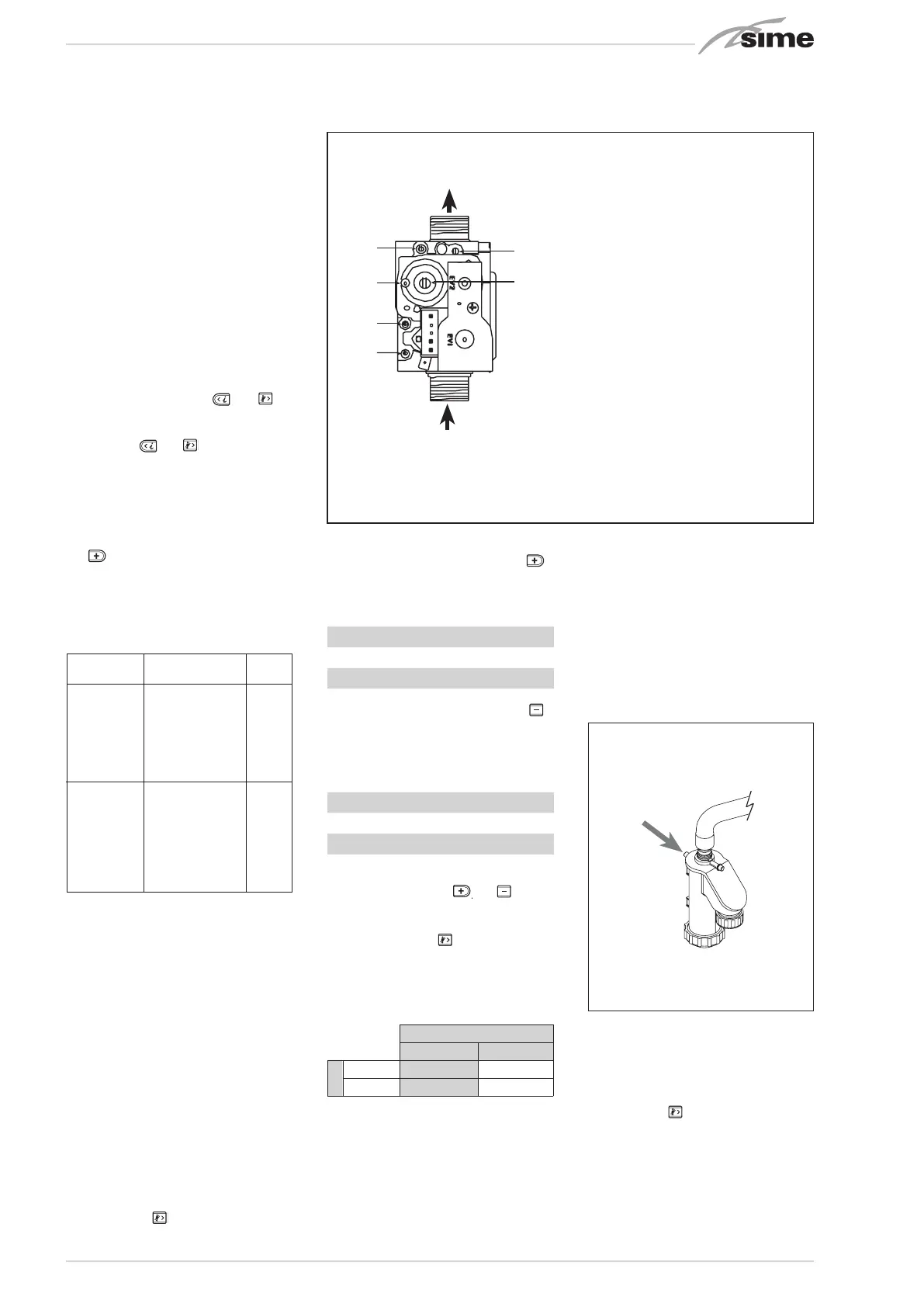
4.1 GAS VALVE (fig. 16)
The generator is supplied as standard with
a gas valve, model SIT 822 NOVAMIX (fig.
16).
4.2 GAS CONVERSION
This operation must be performed by
authorised personnel using original Sime
components.
4.2.1 New fuel configuration
For access to the installer’s parameters,
press simultaneously keys
5
3
1
2
4
and
5
3
1
2
4
for
5 seconds (3 fig. 12).
The parameters will scroll up and down
with the keys
5
3
1
2
4
and
5
3
1
2
4
.
The display pane will show the values of
the parameter PAR 1.
If the generator is a methane (G20) model,
SET 60 will be displayed:
To change the fuel to propane (G31), it is
necessary to set SET 62, by pressing the
key
5
3
1
2
4
.
The standard display will automatically
return after 10 seconds.
The table below shows the SET settings to
enter when the type of gas fuel is changed.
4.2.2 Calibrating the gas valve
pressures
This can only be done using a flue gas ana-
lyser. If the combustion reading is greater
than the acceptable value AND the integ-
rity of the complete flue system and com-
bustion seals have been verified AND the
inlet working gas pressure has been veri-
fied, adjustments to the gas valve can be
made as described below. Make only small
adjustments (1/8 turn max), and allow time
for the combustion analysis to be made
before making further adjustments.
Sequence of operations:
1) Press and hold the button down for a
few seconds
5
3
1
2
4
.
2) Press the button for a few seconds
5
3
1
2
4
.
3) Identify the CO2 values at max. power by
adjusting the shutter (5 fig. 16):
MAX power
CO2 (Methane) CO2 (Propane)
9,0 ±0,2 10,0 ±0,3
4) Press the button for a few seconds
5
3
1
2
4
.
5) Identify the CO2 values at min. power by
adjusting the OFF-SET regulation screw
(6 fig. 16):
MIN power
CO2 (Methane) CO2 (Propane)
9,0 ±0,2 10,0 ±0,3
6) Press the buttons several times to
check the pressures
5
3
1
2
4
and
5
3
1
2
4
change
them if required.
7) Press the button
5
3
1
2
4
once more to quit
the function.
4.3 CO / CO2 RATIO
CO ppm
100 400
CO2 %
NG 9% 0,0011 0,0044
LPG 10% 0,0010 0,0040
4.5 MAINTENANCE (fig. 20)
To ensure correct operation and efficiency
it is important that the boiler is serviced at
regular intervals, at least once a year (this
may also be a condition of the warranty).
Servicing must only be done by a qualified
technician. During the routine service the
condensate drain can be checked, by care-
fully pouring water into the combustion
chamber, while the burner is removed.
Should the boiler not be used for long peri-
ods of time, it is important that the conden-
sate trap is checked and filled if required. It
can be filled via the filling vent (see fig 20).
4.5.1 Chimney sweep function (fig. 21)
To check boiler combustion, press the
installer’s key
5
3
1
2
4
for a few seconds. The
chimney sweep function will switch on and
will continue for 15 minutes.
From that moment, the boiler will start
working in heating mode at maximum
power, with cut off at 80°C and re-ignition
at 70°C (ATTENTION! Ensure adequate
circulation to the heating system is avail-
Fig. 16
7
B
1
2
3
4
5
6
4
5
6
KEY
1 Upstream pressure intake
2 Intermediate pressure intake
3 Air signal inlet (VENT)
4 Downstream pressure intake
5 Shutter
6 OFF-SET
GAS MODEL PAR 1
METHANE 70 BOX ErP 60
(G20)
PROPANE 70 BOX ErP 62
(G31)
Fig. 20
Bekijk gratis de handleiding van Sime Murelle 70 Box ErP, stel vragen en lees de antwoorden op veelvoorkomende problemen, of gebruik onze assistent om sneller informatie in de handleiding te vinden of uitleg te krijgen over specifieke functies.
Productinformatie
| Merk | Sime |
| Model | Murelle 70 Box ErP |
| Categorie | Niet gecategoriseerd |
| Taal | Nederlands |
| Grootte | 8576 MB |


