Sime Murelle 70 Box ErP handleiding
Handleiding
Je bekijkt pagina 19 van 56
19
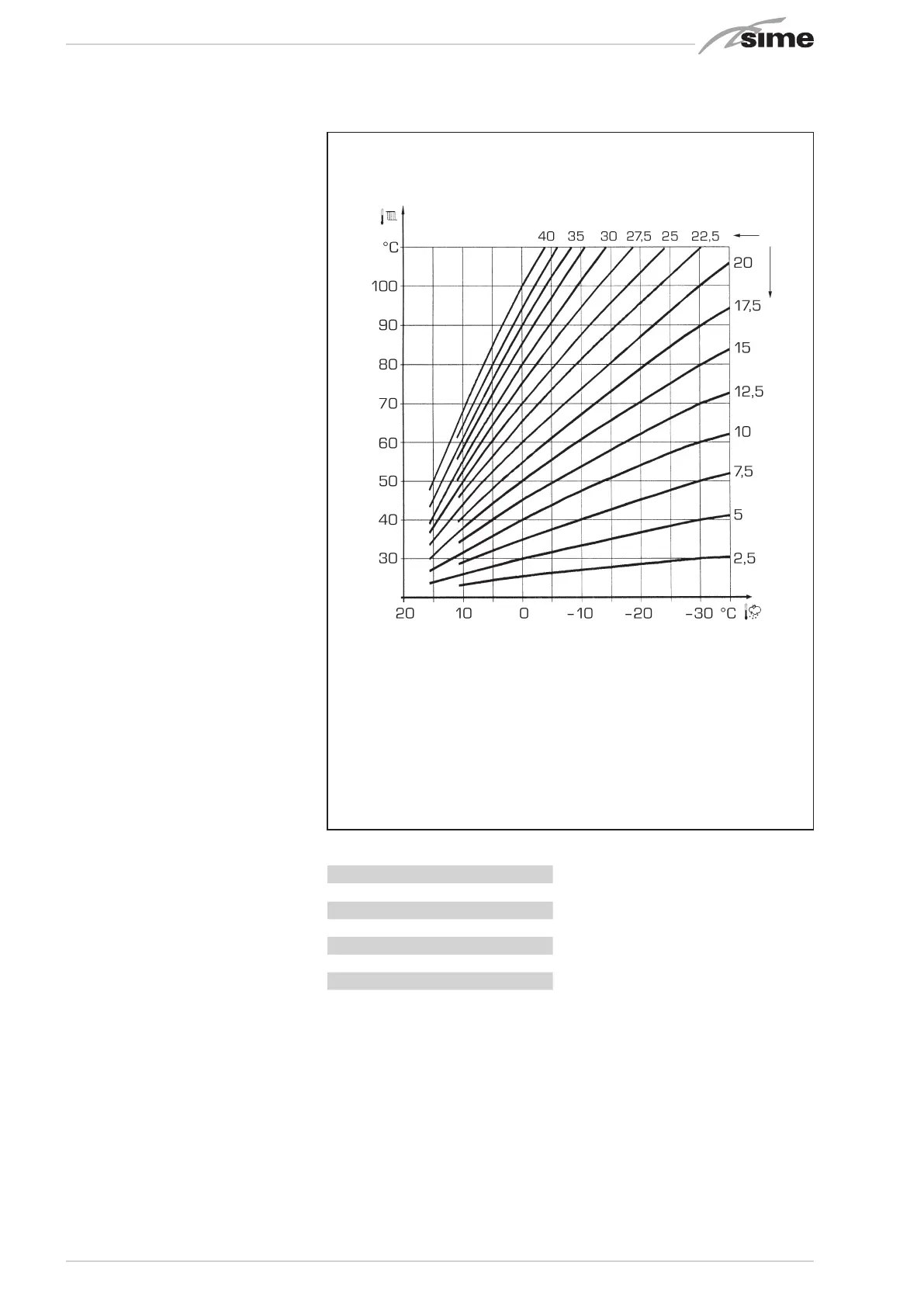
3.4 EXTERNAL SENSOR
fig. 13
If there is an external sensor, the heat-
ing settings SET can be taken from the
climatic curves according to the external
temperature and, in any case, limited to
with the range values described in point
3.3 (parameters PAR 22 for zone 1, PAR 25
for zone 2 and PAR 28 for zone 3).
The climatic curve to be set can be select-
ed from a value of 3 and 40 (at step 1).
Increasing the steepness of the curves
of fig. 13 will increase the output tem-
perature as the external temperature
decreases.
3.5 CARD
FUNCTIONING
The electronic card has the following
functions:
– Antifreeze protection of the heating and
sanitary water circuits (ICE).
– Ignition and flame detection system.
– Control panel setting for the power and
the gas for boiler functioning.
– Anti-jamming for the pump which is
fed for a few seconds after 24 hours of
inactivity.
– Antifreeze protection for boilers with an
accumulation boiling unit.
– Chimney sweep function which can be
activated from the control panel.
– Temperature which can be shifted with
the external sensor connected.
It can be set from the control panel and
is active on the heating systems of both
circuit 1 and circuit 2 and 3.
– Management of 3 independent heating
circuit systems.
– Automatic regulation of the ignition
power and maximum heating.
Adjustments are managed automati-
cally by the electronic card to guarantee
maximum flexibility in use of the sys-
tem.
– Interface with the following electronic
systems: remote control SIME HOME
code 8092280/81, thermal regulator
RVS, connected to a management card
of a MIXED ZONE code 8092275/76,
card SOLAR code 8092277 and card
MODBUS code 8092278.
NOTE: If using RVS 43 set parameter
10 to 3 (PAR 10 = 3).
3.6 TEMPERATURE
DETECTION
SENSOR
Table 4 shows the resistance values of the
heating, DHW and exhaust fumes thermis-
tors.
If the heating flow sensor (SM), heat-
ing return sensor (SR) or the exhaust
fumes sensor (SF) is faulty or open cir-
cuit, the generator will not function.
TABLE 4 (SM - SR - SF sensors)
Temperature (°C) Resistance (Ω)
20 12.090
30 8.313
40 5.828
50 4.161
60 3.021
70 2.229
80 1.669
3.7 ELECTRONIC IGNITION
Ignition and flame detection is controlled by
electrodes on the burner which guarantees
reaction in the case of accidental extinction
or lack of gas within one second.
3.7.1 Functioning cycle
Burner ignition should occur within max. 10
seconds after the opening of the gas valve.
Ignition failure with consequent activation
of block can be due to:
– Lack of gas
The ignition electrode persists in dis-
charging for max. 10 seconds. If after
3 attempts to light the ignition is not
detected the generator will lockout.
This can happen the first time the boiler
is switched on after a long period of inac-
tivity due to the presence of air in the gas
pipes
– No Ionisation
The boiler will make three attempts to
light. If after the third attempt the flame
has no been recognised, the generator
will lockout, ALL 06.
This may be due to a disconnected, worn
or distorted ionisation electrode.
In the case of a sudden loss of voltage, the
burner will immediately switch off.
When voltage returns, the generator will
automatically start up again.
Fig. 13
ATTENTION: curves are calculated at an ambient
temperature of 20°C. The user can act on the boiler
controls to change the environment set for which the
bend has been calculated by ±5°C.
Bekijk gratis de handleiding van Sime Murelle 70 Box ErP, stel vragen en lees de antwoorden op veelvoorkomende problemen, of gebruik onze assistent om sneller informatie in de handleiding te vinden of uitleg te krijgen over specifieke functies.
Productinformatie
| Merk | Sime |
| Model | Murelle 70 Box ErP |
| Categorie | Niet gecategoriseerd |
| Taal | Nederlands |
| Grootte | 8576 MB |


