Sime Murelle 70 Box ErP handleiding
Handleiding
Je bekijkt pagina 17 van 56
17
3.3 ACCESS TO INSTALLER’S
PARAMETERS
For access to the installer’s parameters,
press simultaneously the keys
5
3
1
2
4
and
5
3
1
2
4
or 2 seconds (3 fig. 12).
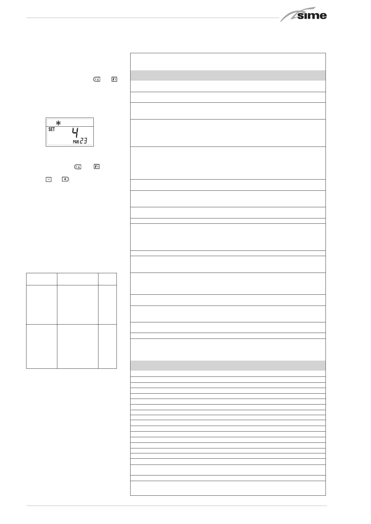
For example, the parameter PAR 23 is dis-
played on the display of the control panel in
the following way:
The parameters scroll forwards and back-
wards with the key
5
3
1
2
4
and
5
3
1
2
4
and the
default parameters can be changed with
the keys
5
3
1
2
4
and
5
3
1
2
4
.
The standard visualisation returns auto-
matically after 60 seconds, or by pressing
one of the control keys (2 fig. 12).
3.3.1 Replacing the board or
RESETTING parameters
If the PCB is replaced or reset, it is neces-
sary to configure PAR 1 and PAR 2 by asso-
ciating the following values to each type of
boiler to be able to restart the boiler:
1. Visualizzazione temperatura
esterna solo con sonda esterna collegata
2. Visualizzazione temperatura sonda
riscaldamento (SM)
3. Visualizzazione temperatura sonda
sanitario (SS) solo per caldaie istantanee
4. Visualizzazione temperatura sonda
ausiliaria o sonda bollitore (SB)
6. Visualizzazione temperatura
riscaldamento riferita al primo circuito
7. Visualizzazione temperatura
riscaldamento riferita al secondo circuito
13. Visualizzazione codice errore
penultima anomalia
14. Visualizzazione numero totale
delle anomalie
9. Visualizzazione numero giri ventilatore in rpm x 100 (es. 4.800 e 1.850 rpm)
10. Visualizzazione ore di funzionamento del bruciatore in h x 100 (es. 14.000 e 10)
11. Visualizzazione numero di accensioni del bruciatore x 1.000 (es. 97.000 e 500)
12. Visualizzazione codice errore
ultima anomalia
15. Contatore accessi parametri
installatore (es. 140 accessi)
5. Visualizzazione temperatura
sonda fumi
8. Visualizzazione corrente
di ionizzazione in µA
16. Contatore accessi parametri
OEM (es. 48 accessi)
PARAMETERS INSTALLER
FAST CONFIGURATION
PAR DESCRIPTION RANGE UNIT OF INC/DEC DEFAULT
MEASUREMENT UNIT SETTING
1 Combustion configuration -- = ND = = “- -”
1 ... 63
2 Hydraulic configuration -- = ND = = “- -”
1 ... 14
3 Timetable 2 programmer 1 =
DHW + Recirc. pump
= = 1
2 = DHW
3 = Recirculation pump
4 Pressure transducer disabler 0 = Disabled = = 3
1 = Enabled 0-4 BAR
2 = Enabled 0-6 BAR
3 = Enabled 0-4 BAR (NO ALL 09)
4 = Enabled 0-6 BAR (NO ALL 09)
5 Assignment of auxiliary relay AUX 1 = Remote alarm NO = = 1
2 = Recirculation pump
3 = Automatic load.
4 = Remote alarm NC
5 = Heat pump
6 = Zone 2 valve
6 Luminous bar indicating presence 0 = Disabled = = 1
of voltage 1 = Enabled
7 Allocation of SIME HOME channels 0 = Not assigned = = 1
1 = Circuit 1
2 = Three-zone circuit
8 Fan rpm Step ignition 0,0 ... 81
rpmx100 0,1 from 0,1 to 19,9 0,0
1 from 20 to 81
9 Long chimneys 0 ... 20 % 1 0
10 Remote control option setting 1 = SIME HOME = = 1
2 = CR 53
3 = RVS 43.143
4 = RVS 46.530
5 = RVS 61.843
11 Correction values external sensor -5 ... +5 °C 1 0
12 Backlighting duration -- = Always sec. x 10 1 3
0 = Never
1 ... 199
13 Modulating pump speed -- = None % 10 Au
Au = Automatic mod.
30...100 = % Settable
modulation
14 Setting second input TA -- = Contact TA -- -- --
5...160 = Input 0...10VDC
15 Cascade address -- = Not enabled -- 1 --
0 = Master
1...7 = Slaves
16 ModBus address -- = Not enabled -- 1 --
1...31 = Slaves
17 ModBus communication configuration 1 ... 30 -- 1 25
19 Type circuit 0 = Two zones -- -- 0
1 = Three zones
D.H.W. - HEATING
PAR DESCRIPTION RANGE UNIT OF INC/DEC DEFAULT
MEASUREMENT UNIT SETTING
20 Minimum heating temperature Zone 1 PAR 64 OEM ... PAR 21 °C 1 20
21 Maximum heating temperature Zone 1 PAR 20 ... PAR 65 OEM °C 1 80
22 Heating curve slope Zone 1 3 ... 40 -- 1 20
23 Minimum heating temperature Zone 2 PAR 64 OEM ... PAR 24 °C 1 20
24 Maximum heating temperature Zone 2 PAR 23 ... PAR 65 OEM °C 1 80
25 Heating curve slope Zone 2 3 ... 40 -- 1 20
26 Minimum heating temperature Zone 3 PAR 64 OEM ... PAR 27 °C 1 20
27 Maximum heating temperature Zone 3 PAR 26 ... PAR 65 OEM °C 1 80
28 Heating curve slope Zone 3 3 ... 40 -- 1 20
29 ∆t heating circuit 10 ... 40 °C 1 20
30 Post-circulation heating time 0 ... 199 Sec. 10 30
31 Maximum heating capacity 30 ... 100 % 1 100
32 Zone 1 pump activation delay 0 ... 199 10 sec. 1 1
33 Start-up delay 0 ... 10 Min. 1 3
34 Additional source activation threshold -- , -10 ... 40 °C 1 “- -”
35 Boiler antifreeze 0 ... +20 °C 1 3
36 External sensor antifreeze -5 ... +5 °C 1 -2
37 Band saturation -- =
Disabled
% 1 100
flowmeter modulation 0 ... 100
38 D.H.W. post-circulation time 0 ... 199 Sec. 1 0
39 Anti-legionella 0 =
Disabled
-- -- 0
(only D.H.W tank)) 1 =
Enabled
GAS MODEL PAR 1
METHANE 70 BOX ErP 60
(G20)
PROPANE 70 BOX ErP 62
(G31)
Bekijk gratis de handleiding van Sime Murelle 70 Box ErP, stel vragen en lees de antwoorden op veelvoorkomende problemen, of gebruik onze assistent om sneller informatie in de handleiding te vinden of uitleg te krijgen over specifieke functies.
Productinformatie
| Merk | Sime |
| Model | Murelle 70 Box ErP |
| Categorie | Niet gecategoriseerd |
| Taal | Nederlands |
| Grootte | 8576 MB |


