Scosche BW2382SRB handleiding
Handleiding
Je bekijkt pagina 5 van 8
5
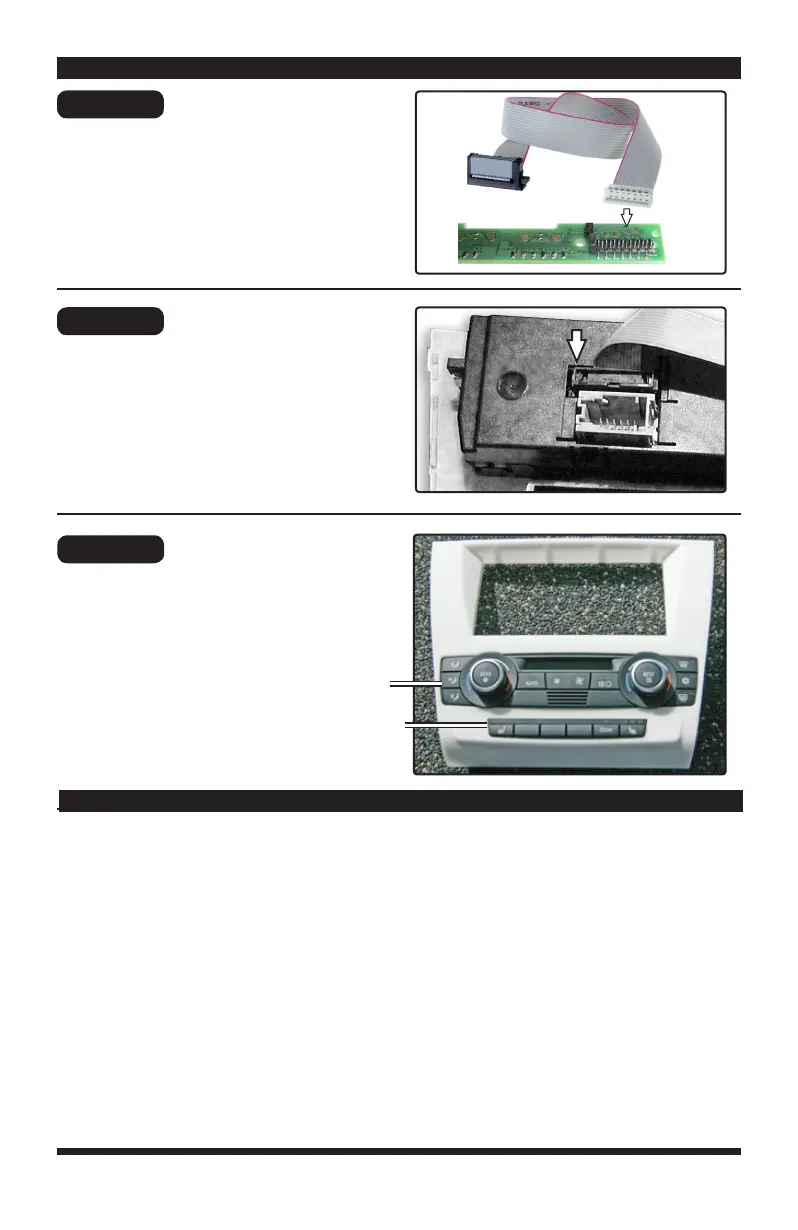
Attach the white connector of the
replacement ribbon cable to the PCB
board and reinstall the PCB into the
switch panel.
Attach the black connector from the
ribbon cable to the air conditioning control
unit.
Transfer and attach the air conditioning
control unit (A) and switch bar (B*) to
the face panel replacement.
*If equipped
Step 12
Step 13
Step 14
Kit Preparation
Kit Preparation
Kit Preparation
A
B*
© 2018 SCOSCHE INDUSTRIES, INC
BW2380SRB 04/18
Preparation cont’d
2008-11 BMW 1-SERIES
NOTE: The RED accessory output wire from the interface is rated at 10A Max output for most
aftermarket head units. We do NOT recommend connecting additional +12A switched
accessories to this output source as that may cause damage to the module itself. If 10A output
is not sucient, then a relay is needed. (Relay not included)
Pink = VSS Vehicle speed pulse signal
Lt. Green = Parking Brake trigger (-12V when park brake ON)
Purple/White = Reverse signal
Pink/Purple = Telephone mute
Yellow = 12V Permanent. Connect directly to battery
White= Left Front Positive (LF+)
White/Black= Left Front Negative (LF-)
Green= Left Rear Positive (LR+)
Green/Black= Left Rear Negative (LR-)
Black= Chassis Ground
Yellow= +12V Constant Power
Red= +12V Accessory
Blue= +12V Power Antenna
(Remote Out)
Gray= Right Front Positive (RF+)
Gray/Black= Right Front Negative (RF-)
Violet= Right Rear Positive (RR+)
Violet/Black= Right Rear Negative (RR-)
Orange= Illumination
WIRING COLOR CODES
Bekijk gratis de handleiding van Scosche BW2382SRB, stel vragen en lees de antwoorden op veelvoorkomende problemen, of gebruik onze assistent om sneller informatie in de handleiding te vinden of uitleg te krijgen over specifieke functies.
Productinformatie
| Merk | Scosche |
| Model | BW2382SRB |
| Categorie | Niet gecategoriseerd |
| Taal | Nederlands |
| Grootte | 2980 MB |


