Handleiding
Je bekijkt pagina 18 van 46
18
English
Installation Procedure
Installation Procedure
Outer Diameter (mm) Torque (N•m)
Ø6.35 14 to 18
Ø9.52 34 to 42
Ø12.70 49 to 61
Ø15.88 68 to 82
Ø19.05 100 to 120
(1 N•m=10 kgf•cm)
NOTE
• If the pipes must be shortened, see Step 6 Cutting and
flaring the pipes on page 17.
2 Be sure to use an insulator thick enough to cover the
refrigerant tube to protect the condensate water on the
outside of the pipe falling onto the floor and to improve
the efficiency of the unit.
3 Cut off any excess foam insulation.
4 Make sure that there are no cracks or waves on the bent
area.
5 It would be necessary to double the insulation thickness
(10 mm or more) to prevent condensation even on the
insulator when if the installed area is warm and humid.
6 Do not use joints or extensions for the pipes connecting
the indoor and outdoor units. The only permitted
connections are those for which the units are designed.
CAUTION
• Connect the indoor and outdoor units using pipes
with flared connections (not supplied). For the
lines, use insulated, unwelded, degreased and
deoxidized copper pipe (Cu DHP type to ISO 1337 or
UNI EN 12735-1), suitable for operating pressures of
at least 4.3 MPa(AC026/035/052/071FE*DKF), 4.5
MPa(AC100/120/140/160FE4DKF) and for a burst
pressure of at least 17.0 MPa. Copper pipe for hydro-
sanitary applications is completely unsuitable.
• For sizing and limits (height difference, line length,
max. bends, refrigerant charge, etc.) see the outdoor
unit installation manual.
• All refrigerant connection must be accessible, in order
to permit either unit maintenance or removing it
completely.
• If the pipes require brazing, make sure that oxygen free
nitrogen (OFN) is flowing through the system.
• Nitrogen blowing pressure range is 0.02 to 0.05 MPa.
Step 8 Performing the gas leak test
To identify potential gas leaks on the indoor unit, inspect the
connection area of each refrigerant pipe using a leak detector
for R-32.
Before recreating the vacuum and recirculating the refrigerant gas,
pressurize the whole system with nitrogen (using a cylinder with a
pressure reducer) at a pressure above0.2 MPa,less than4.0 MPa in
order to immediately detect leaks on the refrigerant fittings.
Made vacuum for 15 minutes and pressurizing system with
nitrogen.
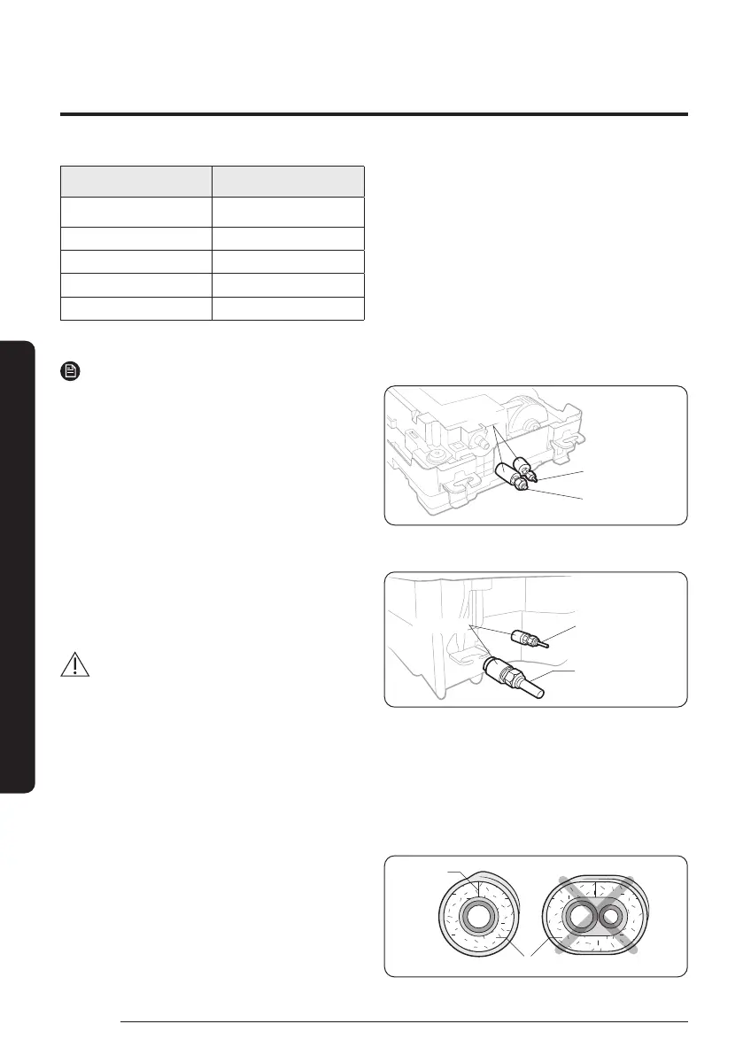
1 way Cassette
Insulator
Liquid side
Gas side
4 way Cassette
Liquid side
Gas side
Insulator
Step 9 Insulating the refrigerant pipes
Once you have checked that there are no leaks in the system,
you can insulate the piping and hose.
1 To avoid condensation problems, place Acrylonitrile
Butadien Rubber separately around each refrigerant pipe.
No gap
NBR
DB68-13503A-01_IM_CAC R-32 WindFree1_4way_EA_EN_.indd 18DB68-13503A-01_IM_CAC R-32 WindFree1_4way_EA_EN_.indd 18 2025-04-08 오전 8:53:212025-04-08 오전 8:53:21
Bekijk gratis de handleiding van Samsung AC035FE1DKF, stel vragen en lees de antwoorden op veelvoorkomende problemen, of gebruik onze assistent om sneller informatie in de handleiding te vinden of uitleg te krijgen over specifieke functies.
Productinformatie
| Merk | Samsung |
| Model | AC035FE1DKF |
| Categorie | Airco |
| Taal | Nederlands |
| Grootte | 4702 MB |


