Planet IGS-4215-24T4X handleiding
Handleiding
Je bekijkt pagina 52 van 380
User’s Manual of IGS-4215 DIN-rail Series
52
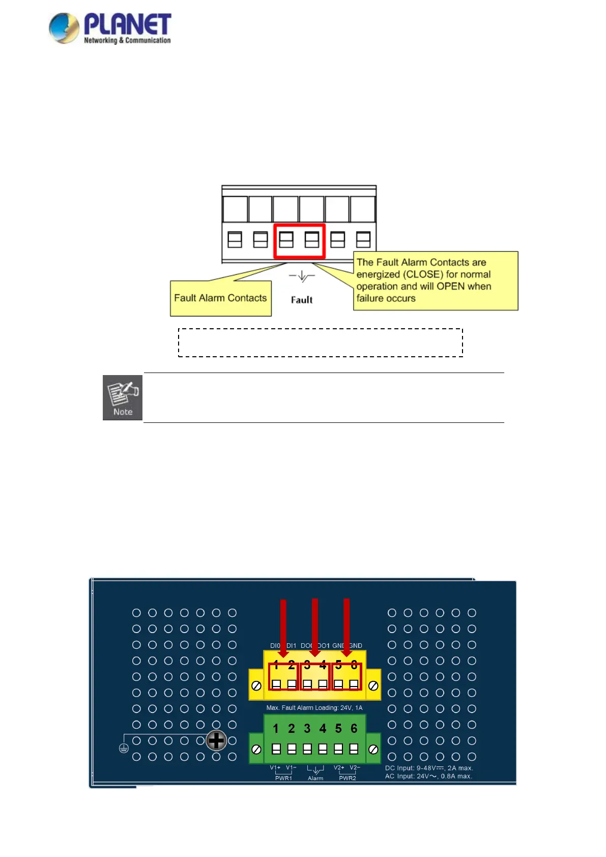
2.1.6 Wiring the Fault Alarm Contact
The fault alarm contacts are centrally located within the terminal block connector, as illustrated in the provided diagram. When
wires are connected, the Industrial Managed Switch monitors for power failures or port link failures (applicable to managed
models), triggering an open circuit in response to these faults. The accompanying diagram offers a practical example of how to
wire these fault alarm contacts.
1. The wire gauge for the terminal block should be in the range of 12 ~ 24 AWG.
2. Alarm relay circuit accepts a maximum of up to 24V, 1A current.
2.1.7 Wiring the Digital Input/Output
The 6-contact terminal block connector on the rear panel of IGS Series is used for Digital Input and Digital Output. Please
follow the steps below to insert wire.
1. The IGS-4215 series offers two DI and DO groups. 1 and 2 are DI groups; 3 and 4 are DO groups; and 5 and 6 are GND
(ground).
Figure 2-1-7a Wiring Digital Inputs/Outputs
Insert the wires into the fault alarm contacts
DI
DO
GND
Bekijk gratis de handleiding van Planet IGS-4215-24T4X, stel vragen en lees de antwoorden op veelvoorkomende problemen, of gebruik onze assistent om sneller informatie in de handleiding te vinden of uitleg te krijgen over specifieke functies.
Productinformatie
| Merk | Planet |
| Model | IGS-4215-24T4X |
| Categorie | Niet gecategoriseerd |
| Taal | Nederlands |
| Grootte | 74502 MB |


