Phoenix Contact SCK-M-U-1500V handleiding
Handleiding
Je bekijkt pagina 27 van 128
SOLARCHECK string voltage measurement with SCK-M-U-1500V
105608_en_02 PHOENIX CONTACT 27
Calculation basis for Table 4-1 and Table 4-2:
The maximum measured value deviation of 1% (of the measuring range final value) is based
on the 100 V DC to 1500 V DC system voltage range. The deviation may be greater below
100 V DC.
4.1.2 Parallel connection of multiple voltage measuring devices
in a system
Due to the circuit architecture in the device, the voltage measuring input is connected to
ground via the internal impedances. Resistance Rx is 20 MΩ respectively. If multiple volt-
age measuring devices are connected to the same generator in parallel, these impedances
are also connected in parallel. This results in an overall reduced impedance of the generator
to ground. This can affect the response of any ground fault detection in the system.
The impedances of the voltage measuring devices used within a generator (per inverter in-
put) therefore have to be taken into consideration when defining the threshold values for
ground fault detection.
The following impedances result depending on the number of voltage measurements con-
nected in parallel in a system.
If:
(0 < U+ < 1500 V) and
(0 < U- < -1500 V) and
(0 < Difference (U+, U-) < 1500 V
Then
Analog OUT:
Difference (U+, U-) x 8 V
+ 2 V
1500 V
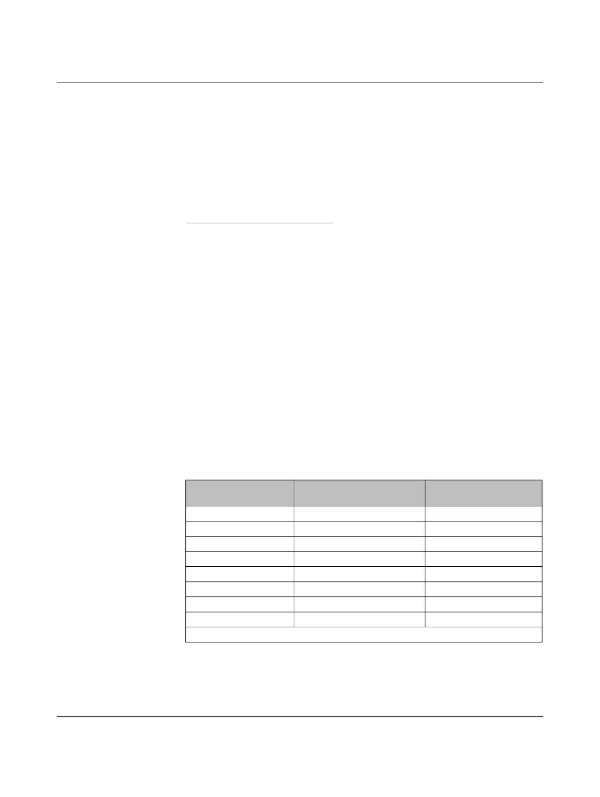
Table 4-3 Impedances
Number of parallel
voltage measurements
Individual impedance (+ PE) Total impedance (+ PE)
1 20 MΩ 20 MΩ
2 20 MΩ 10 MΩ
4 20 MΩ 5 MΩ
8 20 MΩ 2.5 MΩ
16 20 MΩ 1.25 MΩ
32 20 MΩ 0.625 MΩ
64 20 MΩ 0.313 MΩ
128 20 MΩ 0.156 MΩ
…
Bekijk gratis de handleiding van Phoenix Contact SCK-M-U-1500V, stel vragen en lees de antwoorden op veelvoorkomende problemen, of gebruik onze assistent om sneller informatie in de handleiding te vinden of uitleg te krijgen over specifieke functies.
Productinformatie
| Merk | Phoenix Contact |
| Model | SCK-M-U-1500V |
| Categorie | Niet gecategoriseerd |
| Taal | Nederlands |
| Grootte | 11551 MB |


