Phoenix Contact FL SWITCH EP7400 handleiding
Handleiding
Je bekijkt pagina 17 van 46
Components
4083_en_C PHOENIX CONTACT 17/46
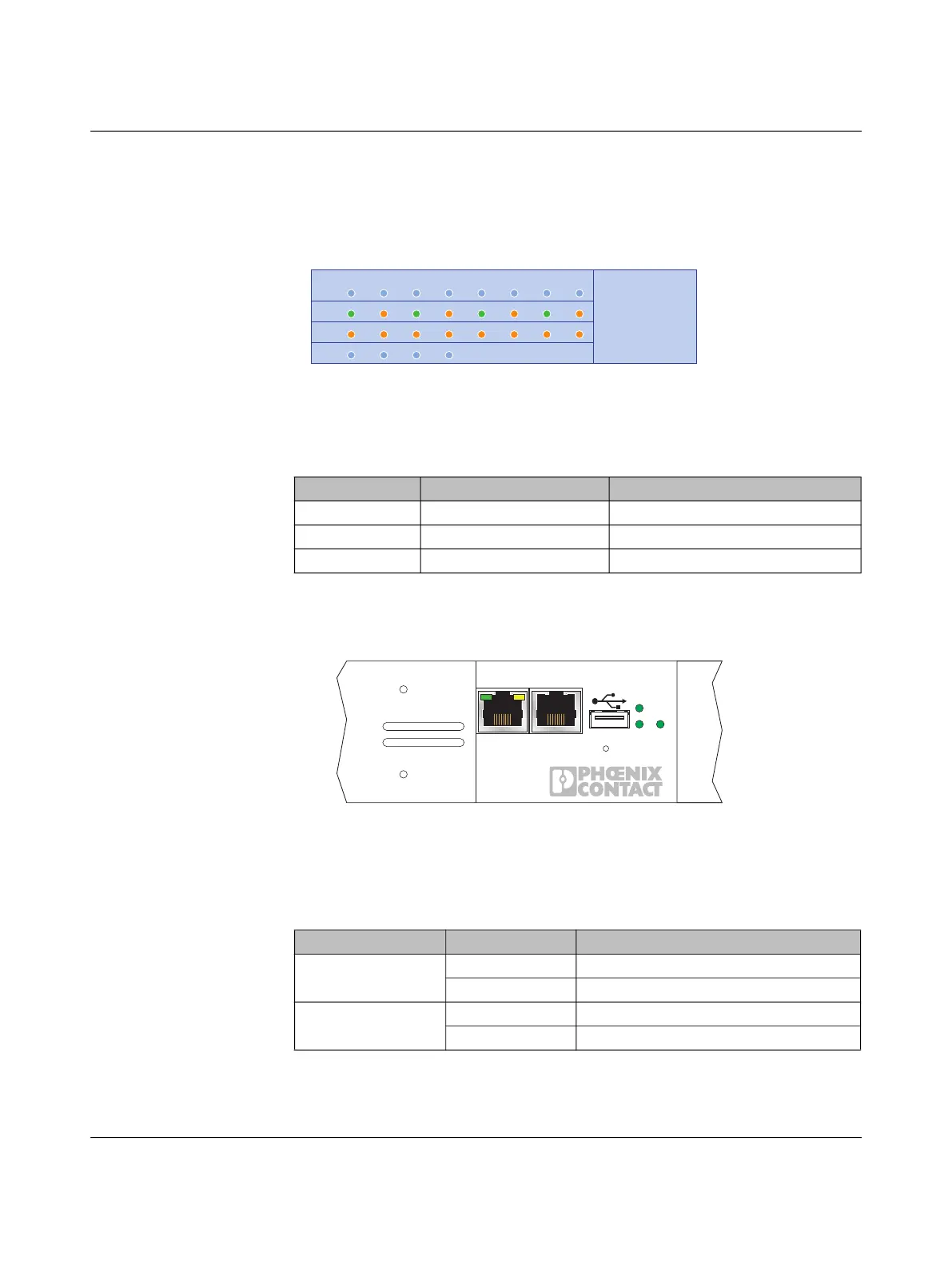
3.3.1 Status indicators
LCD display
Figure 3-7 LCD display of port status
The LCD displays the status of each port for the installed port/line modules. It also dis-
plays the hardware and firmware revision status during boot up.
Front LEDs
Figure 3-8 LED status indicators, front view
The front LEDs indicate that status of the installed power supply modules and the oper-
ating status (alarms) of the FL SWITCH EP7…. An LED at each port on each module indi-
cates the port link and activity of that port.
Table 3-6 Port LCD status
Color RJ45 port SFP port
Green Link established Link established
Red – SFP module inserted, not linked
Grey No link or cable SFP module is not present
Table 3-7 Front LED indicators
Label Color Indication
PS1 and PS2 Green Normal operating status
Off No power or module not installed
Alarm Green Alarms cleared or acknowledged
Red Active alarms
LM1:
LM2:
LM3:
LM4:
12345678
CONSOLE
PS2
RESET
PS1
ALARM
MGMT
1
2
SD CARD
Bekijk gratis de handleiding van Phoenix Contact FL SWITCH EP7400, stel vragen en lees de antwoorden op veelvoorkomende problemen, of gebruik onze assistent om sneller informatie in de handleiding te vinden of uitleg te krijgen over specifieke functies.
Productinformatie
| Merk | Phoenix Contact |
| Model | FL SWITCH EP7400 |
| Categorie | Niet gecategoriseerd |
| Taal | Nederlands |
| Grootte | 4097 MB |


