Phoenix Contact FL SWITCH EP7400 handleiding
Handleiding
Je bekijkt pagina 11 van 46
Components
4083_en_C PHOENIX CONTACT 11/46
3 Components
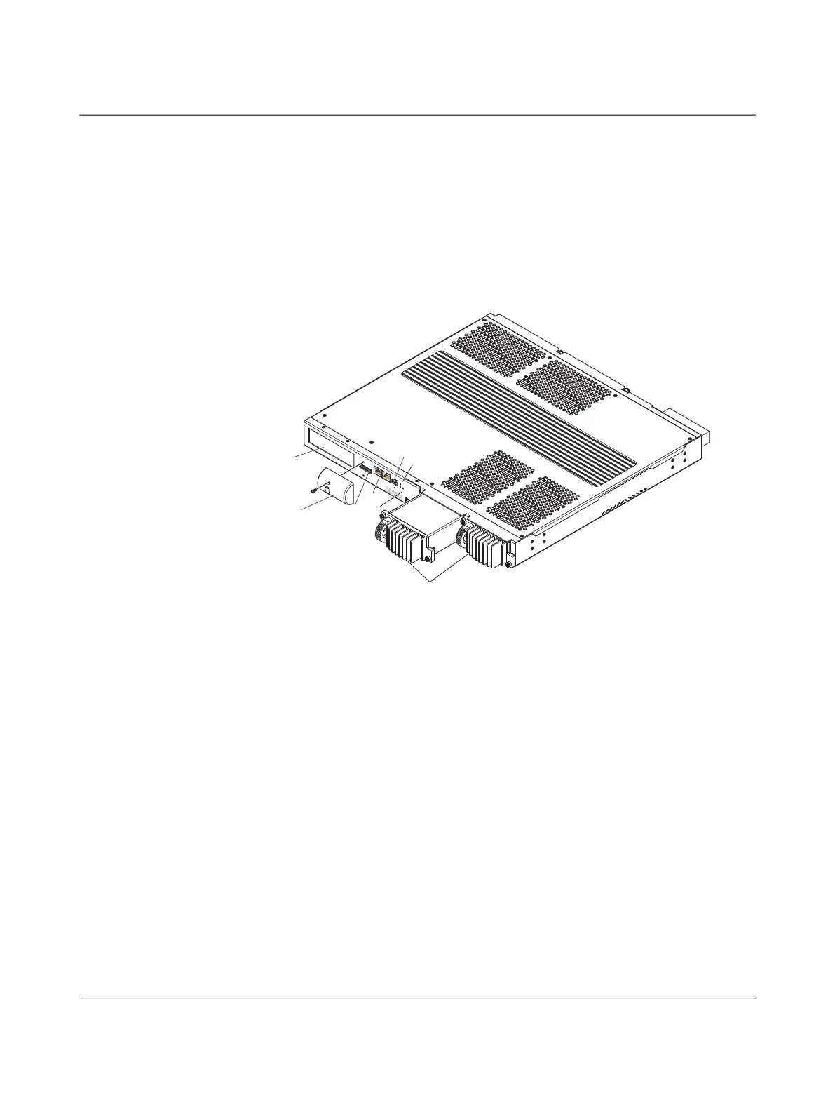
3.1 Switch base
The switch base FL SWITCH EP7… installs in a standard 19-inch rack using 1U vertical
space with an additional unit (or 44 mm) of space required for cooling above and below
the switch.
Figure 3-1 FL SWITCH EP7… view from front
Heat generated by the switch is channeled outwards from the enclosure. For improved
convectional airflow, make sure there is at least one rack unit (1U) or 44 mm of space
around all sides of the device or between the devices on the rack.
Forced airflow is not required. However, any increase in airflow will result in a reduction
of ambient temperature and improve the long-term reliability of the equipment mounted
in the rack space.
The color LCD displays switch revision information and port status.
The SecureDigital (SD) port cover covers the following:
– SD card slot #1 (top) is for factory use and is disabled.
– SD card slot #2 (bottom) is available for storing up to 32 GB of Syslog event files.
– The management port, a 10/100 Base-T Ethernet port, that is used as an out-of-band
factory service port. It is disabled by default and not available for user access.
– Power status LEDs indicate the status of the installed power supply modules.
CONS
OLE
MGMT
PS2
PS2
PS1
RES
ET
1
2
SD CA
R
D
PS1
ALA
RM
SD
1 LCD screen
2 SD port cover
3 SD port
4 Management and console ports
5 USB port
6 Power status LEDs
7 Alarm LED
8 Power supply modules
1
2
3
4
5
6
7
8
Bekijk gratis de handleiding van Phoenix Contact FL SWITCH EP7400, stel vragen en lees de antwoorden op veelvoorkomende problemen, of gebruik onze assistent om sneller informatie in de handleiding te vinden of uitleg te krijgen over specifieke functies.
Productinformatie
| Merk | Phoenix Contact |
| Model | FL SWITCH EP7400 |
| Categorie | Niet gecategoriseerd |
| Taal | Nederlands |
| Grootte | 4097 MB |


