Phoenix Contact FL PN/PN SDIO-2TX/2TX handleiding
Handleiding
Je bekijkt pagina 35 van 94
Description of the FL PN/PN SDIO-2TX/2TX
8220_en_06 PHOENIX CONTACT 35
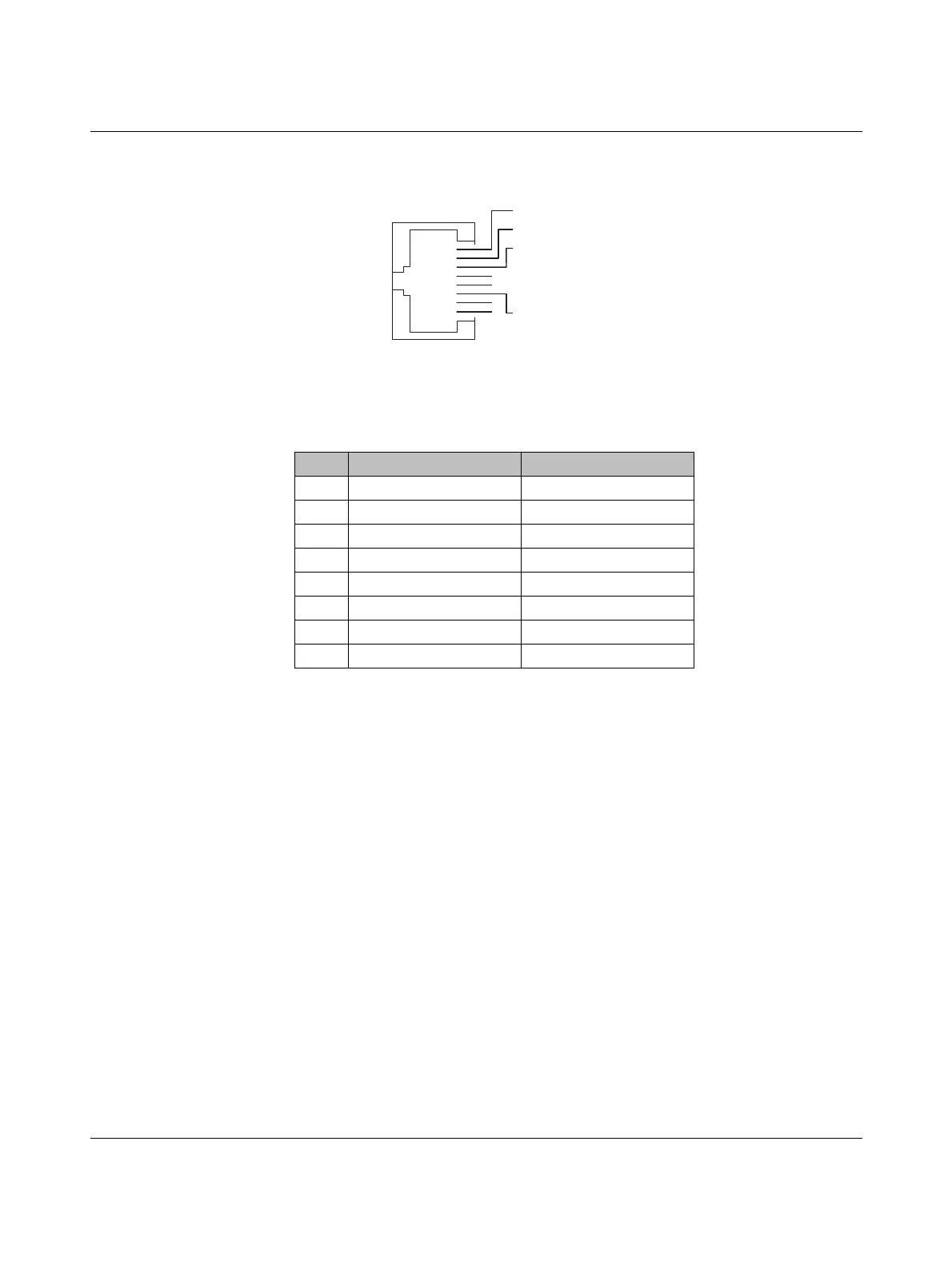
The figure below shows the pin assignment of the Ethernet interfaces.
Figure 2-9 Pin assignment of the Ethernet interfaces (RJ45 sockets)
2.11 Power supply
The safe PROFINET gateway is operated using a 24 V DC voltage which is supplied
redundantly.
2.11.1 Power supply principle
The figure below shows the principle for the redundant power supply of the safe PROFINET
gateway. Supply the FL PN/PN SDIO-2TX/2TX with 24 V DC each at voltage inputs
U
S1
/U
S2
using a COMBICON plug-in connector (see Figure 2-11 on page 36). Input
voltages U
S1
/U
S2
are electrically isolated inside the device.
The electronics inside the device monitor both input voltages. They make sure that the safe
PROFINET gateway is supplied with voltage with an output value that is within the valid
range.
For more detailed information on the insulation voltage/electrical isolation and on the input
voltage range, please refer to “Technical data” on page 61.
Table 2-5 Pin assignment of the Ethernet interfaces (RJ45 sockets)
Pin Assignment Meaning
1 TD+ Transmit data+
2 TD- Transmit data-
3 RD+ Receive data+
4– Reserved
5– Reserved
6 RD- Receive data-
7– Reserved
8– Reserved
RJ45
Pin 1
Pin 2
Pin 3
Pin 4
Pin 5
Pin 6
Pin 7
Pin 8
Bekijk gratis de handleiding van Phoenix Contact FL PN/PN SDIO-2TX/2TX, stel vragen en lees de antwoorden op veelvoorkomende problemen, of gebruik onze assistent om sneller informatie in de handleiding te vinden of uitleg te krijgen over specifieke functies.
Productinformatie
| Merk | Phoenix Contact |
| Model | FL PN/PN SDIO-2TX/2TX |
| Categorie | Niet gecategoriseerd |
| Taal | Nederlands |
| Grootte | 7175 MB |


