PCE Instruments PCE-SCI-L handleiding
Handleiding
Je bekijkt pagina 6 van 24
6
PCE Instruments
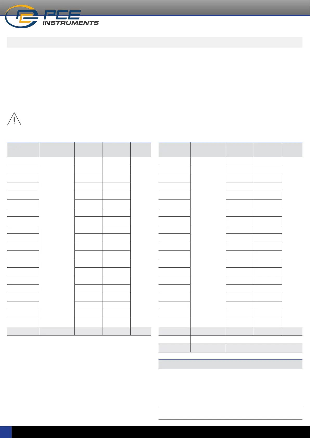
Table 8 | Predened conguration codes for load cells - Input / Output
Input signal
range
Type of signal Output 4/20 mA
Code
Output 0/10 Vdc
Code
See section
...
0/5 mVdc
load cell
signal
010 110
10.1
0/10 mVdc 011 111
0/15 mVdc 012 112
0/20 mVdc 013 113
0/25 mVdc 014 114
0/30 mVdc 015 115
0/40 mVdc 016 116
0/50 mVdc 017 117
0/60 mVdc 018 118
0/70 mVdc 019 119
0/80 mVdc 020 120
±5 mVdc 021 121
±10 mVdc 022 122
±20 mVdc 023 123
±30 mVdc 024 124
±40 mVdc 025 125
±50 mVdc 026 126
±60 mVdc 027 127
±70 mVdc 028 128
±80 mVdc 029 129
Reserved 030 to 049 130 to 149
8. Predened conguration codes
Select the desired code for your application, and check the following
sections for more information:
• for information on how to activate a code, see section 13.1
• to customize the input and output signals, see section 13.4
Notes
• Code ‘uSEr’ indicates that a user custom conguration is active, and it does not
match any of the listed codes This code is non-selectable, for information only.
Example: select code ‘013’ for 0/20 mVdc=4/20 mA, the instrument reads code
‘013’. Later, congure the input to 0/17 mVdc=4/20 mA, this does not match a listed
code, and the instrument reads ‘uSEr’. Or change the output to 0/20 mVdc=1/5 Vdc,
this does not match a listed code, and the instrument reads ‘uSEr’.
• Code ‘----’ identies the end of the list, it follows code ‘199’ and the list
continues with code ‘010’. Select ‘----’ to exit the list without applying changes.
To calculate the optimal input signal range for your load cell,
see section 7.7.
The instrument can be congured to measure millivolt in differential
mode. Activating the millivolt mode disables de excitation voltage and
disables the ‘sense’ compensation for changes at the excitation voltage.
The instrument works as a pure differential millivolt signal converter.
Select the ‘Predened conguration code’ according to your maximum
millivolt signal (see Table 9).
The instrument accepts up to 4 standard 350 Ohms load cells. The
instrument provides 5 Vdc excitation voltage. Calculate the maximum
output signal generated by your load cell, and select the ‘Predened
conguration code’ accordingly (see Table 8).
Table 9 | Predened conguration codes for millivolt signals - Input / Output
Input signal
range
Type of signal Output 4/20 mA
Code
Output 0/10 Vdc
Code
See section
...
0/5 mVdc
millivolt
signal
050 150
10.2
0/10 mVdc 051 151
0/15 mVdc 052 152
0/20 mVdc 053 153
0/25 mVdc 054 154
0/30 mVdc 055 155
0/40 mVdc 056 156
0/50 mVdc 057 157
0/60 mVdc 058 158
0/70 mVdc 059 159
0/80 mVdc 060 160
±5 mVdc 061 161
±10 mVdc 062 162
±20 mVdc 063 163
±30 mVdc 064 164
±40 mVdc 065 165
±50 mVdc 066 166
±60 mVdc 067 167
±70 mVdc 068 168
±80 mVdc 069 169
Reserved 070 to 099 170 to 199
(End of list) ‘----’ (see notes below)
(Custom selection)
‘uSEr’ (see notes below)
Bekijk gratis de handleiding van PCE Instruments PCE-SCI-L, stel vragen en lees de antwoorden op veelvoorkomende problemen, of gebruik onze assistent om sneller informatie in de handleiding te vinden of uitleg te krijgen over specifieke functies.
Productinformatie
| Merk | PCE Instruments |
| Model | PCE-SCI-L |
| Categorie | Niet gecategoriseerd |
| Taal | Nederlands |
| Grootte | 4371 MB |


