PCE Instruments PCE-SCI-E handleiding
Handleiding
Je bekijkt pagina 3 van 24
3
PCE Instruments | www.pce-instruments.com
If this is the rst time you are conguring the instrument, below are
the steps to follow during a rst installation. Read all the
manual sections in order to have a full and clear view of the
characteristics of the instrument. Do not forget to read the
installation precautions at section 17.
1. Install the instrument at the DIN rail
2. Read how to operate the instrument (see section 10)
3. Connect the input, the output and the power terminals (see section 9).
4. Congure the input and output signals
• choose a predened conguration code (see section 8)
• introduce the code at the instrument (see section 13.1)
5. If
needed, customize the input and output signal ranges (see section 13.4)
6. If needed, congure the display reading (see section 13.5), the key ‘UP’
(5) ‘force’ menu (see section 13.6), and the key ‘LE’ (3) ‘messages’ function
(see section 13.7),
7. If needed, block access to the ‘conguration menu’ (see section 13.8)
4. Installation and start-up
To measure electrical signals in AC and DC and provide a standard
process signal in 4/20 mA or 0/10 Vdc. Accepts signals from current
shunts, signals from DC batteries of 12 Vdc, 24 Vdc, 48 Vdc, ..., signals
from tachometric dynamos of ±60 Vdc, power lines of 230 Vac, 115 Vac,
48 Vac, 24 Vdc, AC leak currents of down to 5 mAac and below, 50 and
60 Hz frequency signals from AC power lines, signals from X/5 and X/1
current transformers.
5. Typical applications
The instrument includes a congurable ‘messages’ function that provides
advanced information about the system, available to the operator with a
single click at the front key ‘LE’ (3).
This information is helpful during start-up, installation, system
verication, routine maintenance and troubleshooting, as messages and
values provide information on the actual input and output signal value,
actual percentage of the input signal compared to the full scale and
scaled process values.
This information is available at any time, and is displayed sequentially
when requested. Access to this information reduces maintenance
time, improves time invested in failure location, and helps for an easy
resolution of the problem.
Additionally, each instrument can be assigned a custom label code of up
to 8 characters (see Table 1), that can be displayed at the front display
or at the messages sequence, making system identication of each
instrument an easy task.
To congure the ‘messages’ function, see section 13.7.
The instrument includes a congurable ‘SOS mode’ function that provides
a way to manually congure a xed output signal. This output signal
remains xed, independent of the input signal value or sensor state.
This function allows to perform urgent maintenance or repair tasks at the
input section of the system, for example replacing sensors, shunts, or
deactivating power lines, while the instrument still provides a controlled
signal that allows for the process to continue its activity, under human
surveillance. When the maintenance or repair task has been performed,
the instrument can be taken back to the standard working mode, where
the output signal is proportional to the input.
When manually activated, the ‘SOS mode’ generates the output signal
congured, and the front display remains ashing with the message
‘SoS’. All other systems are disabled, which means that :
• no error messages will be shown on display
• no key ‘UP’ (5) ‘fast access’ menu is accessible
• no key ‘LE’ (3) ‘messages’ function is accessible
• no ‘Eco’ mode activates
Only key ‘SQ’ (<) is accessible, to access the ‘conguration menu’
(eventually this access can be password locked) in order to deactivate
the ‘SOS mode’. Deactivation of ‘SOS mode’ must be performed manually
by conguring the function to ‘oFF’.
To congure the ‘SOS mode’ function, see section 13.8.
6. SOS mode
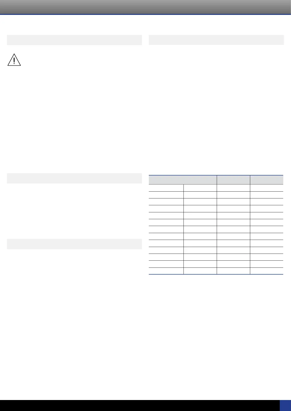
Table 1 | Available label codes
Letters Numbers
Special
A
n 0
-
b o 1 _
c P 2 .
d q 3 (blank)
E r 4
F S 5
G t 6
h u 7
I V 8
J W 9
K X
L Y
M Z
7. Messages
Labeling examples: for an application with multiple engine control,
where voltage and frequency are being measured for three engines, and
converted to 4/20 mA for retransmission to PLC or SCADA. Six PCE-SCI-E
converters are being used, to measure 0/300 Vac and 45/55 Hz. Each
PCE-SCI-E can be congured the following label for easy identication :
• Label for engine 1 frequency measurement : Eng1.hZ
• Label for engine 2 frequency measurement : Eng2.hZ
• Label for engine 3 frequency measurement : Eng3.hZ
• Label for engine 1 voltage measurement : Eng1.Vac
• Label for engine 2 voltage measurement : Eng2.Vac
• Label for engine 3 voltage measurement : Eng3.Vac
Bekijk gratis de handleiding van PCE Instruments PCE-SCI-E, stel vragen en lees de antwoorden op veelvoorkomende problemen, of gebruik onze assistent om sneller informatie in de handleiding te vinden of uitleg te krijgen over specifieke functies.
Productinformatie
| Merk | PCE Instruments |
| Model | PCE-SCI-E |
| Categorie | Niet gecategoriseerd |
| Taal | Nederlands |
| Grootte | 4240 MB |


