Parkside PIFDS 120 B2 handleiding
Handleiding
Je bekijkt pagina 18 van 69
18 GB/IE/NI/CY
recommended to carry out the work with
an additional person.
Push the flux cored wire through the wire
feed guide
31
(see Fig. M).
Guide the wire along the feed roll
19
and push it into the cable assembly
holder
32
(see Fig. N).
Swivel the thrust roller unit
28
towards
the feed roll
19
(see Fig. O).
Mount the adjustment
27
screw (see Fig.
O).
Set the counter pressure with the
adjustment screw. The welding wire must
be firmly positioned between the thrust
roller and feed roll
19
in the upper guide
without being crushed (see Fig. O).
Switch on the welder on the main
5
switch.
Press the torch button
11
.
Now the wire feed system pushes the
welding wire through the cable assembly
12
and the torch
10
.
As soon as 1 – 2 cm of the wire pro-
trudes from the torch neck
33
, release the
torch
11
button again (see Fig. P).
Switch off the welder on the main switch.
Screw the welding nozzle
15
back on.
Make sure that the welding nozzle
15
matches the diameter of the welding
wire used (see Fig. Q). When using the
delivered welding wire (Ø 0.9 mm), the
welding nozzle
15
with the labelling
0.9 mm must be used.
Screw the burner nozzle
9
back onto
the torch neck
33
(see Fig. R).
Always unplug the mains
plug from the socket prior to each mainte-
nance task or preparatory work in order to
prevent the risk of an electric shock, injury or
damage.
z Using the device
z Switching the device on
andoff
Switch the welder on and off on the main
5
switch. If you do not intend to use the
welder for an extended period, remove
the plug from the power socket. This is
the only way to completely de-energise
the device.
z Setting the welding current
and wire feed
The control dial
7
on the front of the welder
can be used to adjust the material thickness
to be welded. Power and wire feed are
controlled automatically.
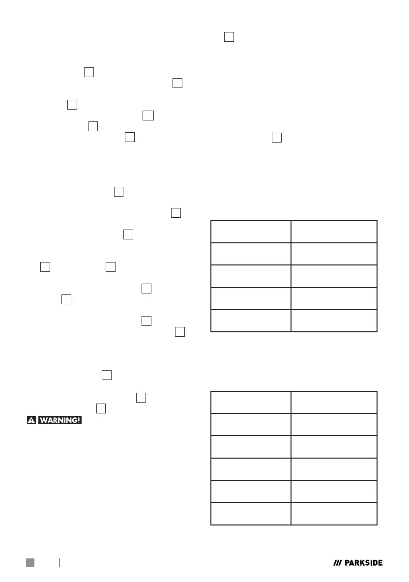
Recommended welding wire diameter for the
material thickness given
Welding wire
diameter
Thickness of the
workpiece
0.6 mm 0.8–1.5 mm
0.8 mm 0.8–2.0 mm
0.9 mm 0.8–3.0 mm
1.0 mm 1.0–3.0 mm
The following table shows the welding
current range, depending on the setting
selected for the material thickness:
Material thickness
setting
Welding current
range
0.8 mm 20-45 A
1.5 mm 45-60 A
2 mm 75-90 A
2.5 mm 90-110 A
3 mm 110-120 A
Bekijk gratis de handleiding van Parkside PIFDS 120 B2, stel vragen en lees de antwoorden op veelvoorkomende problemen, of gebruik onze assistent om sneller informatie in de handleiding te vinden of uitleg te krijgen over specifieke functies.
Productinformatie
| Merk | Parkside |
| Model | PIFDS 120 B2 |
| Categorie | Niet gecategoriseerd |
| Taal | Nederlands |
| Grootte | 8130 MB |


