Optex SIP-5030-IP-BOX handleiding
Handleiding
Je bekijkt pagina 3 van 12
- 2 -
- 3 -
ENGLISH FRANÇAIS DEUTSCH ITALIANO ESPAÑOL
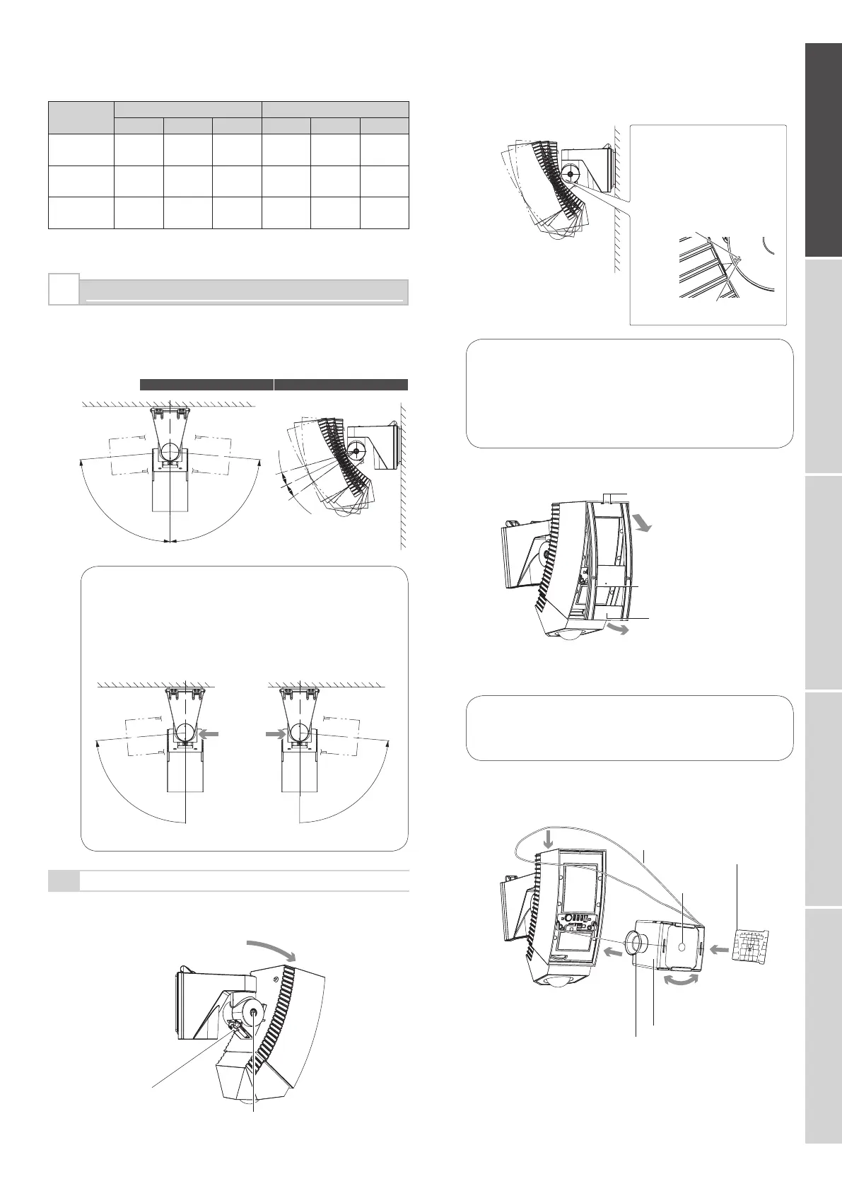
DETECTION AREA SETTING
You can adjust the detection area by 90 degrees in a horizontal
direction and by 10 degrees in a vertical direction.
Correct the vertical detection angle according to the mounting
height of the sensor unit.
Applicable
models
SIP-5030 SIP-100
10°
10°
85°
85°
Cautions>>
To rotate the main unit counterclockwise, loosen the
RHside adjustment screw. To rotate the main unit
clockwise, loosen the LH-side adjustment screw.
Otherwise, you may find it difficult to tighten or you may
find that you cannot tighten the adjustment screw when
you are securing the main unit.
To rotate the unit counterclockwise
To rotate the unit clockwise
4-1
Main Detection Area Setting
Adjust the angle of the main unit in a horizontal direction so
that you can cover the desired detection area.
4
Power wires should not exceed the following lengths.
WIRE SIZE
SIP-5030
SIP-100
12V DC
14V DC 24V AC 12V DC 14V DC 24V AC
0.33 mm
2
(AWG22)
480
(1570)
640
(2100)
1370
(4490)
410
(1350)
550
(1800)
1280
(4200)
0.52 mm
2
(AWG20)
760
(2490)
1010
(3310)
2160
(7090)
650
(2130)
860
(2820)
2020
(6630)
0.83 mm
2
(AWG18)
1210
(3970)
1610
(5280)
3450
(11320)
1030
(3380)
1380
(4530)
3220
(10560)
m (ft.)
Adjust the angle of the main unit in a vertical direction so
that you can cover the desired detection area.
Cautions>>
If the mounting wall is at an angle, the arrow of the
main unit may exceed the top or bottom limit of “Angle
adjustment guide”. Always check this using the area
viewfinder or the walk tester. If the detection area is too
high or too low, an object outside the detection area may
be detected or incorrect object detection may occur.
Remove the cover.
Cautions>>
The cover is linked to the main unit by nylon wire loop so
that the cover does not fall. Do not pull the cover using
excessive force.
Mount the area viewfinder.
F2
F3
F4
F5
E2
E3
E4
E5
D1
D2
D
3
D
4
D5
D6
C1
C2
C3
C4
C5
C6
B1
B
2
B
3
B
4
B5
7
8
9
10
1
2
3
4
5
6
F1
F6
E1
E6
B6
5
0
3
0
(
5
2
1
2
0
6
)
(2)
(3)
(4)
(1)
Hooks
3 Slide the cover downward
and release the hooks.
1 Loosen two xing screws for
the cover and pull out the
cover until it stops.
Cover
2 Hold the heads of both cover xing screws
with your hands, and pull down and remove
the bottom section of the cover from the
main unit.
Adjustment
screw
3 Rotate the main unit.
2 Loosen the adjustment screw.
4 Tighten the adjustment screw slightly.
1 Loosen the xing
screw for the base.
Area plate
(an accessory)
Determine the
detection direction
(see Step 5-1).
Put the red string
round the main unit.
Insert and
mount to
the main
unit.
Red string to
hold the main unit
Center circle
of the lens
Area viewnder AVF-1 (optional)
Inspection window
Insert the area
plate into the slot.
* Peel off the
protection
seal from
both faces
of the area
plate.
1
2
3
4
When mounted at a height of
2.3 meters (7.6ft.)
When mounted at a height of
4.0 meters (13ft.)
Align the arrow of the main
unit with the “Angle adjustment
g u i d e ” of t h e a d j u s t m e n t
screw. The main unit is usually
adjusted within the width of this
guide.
SIP5030_EN.indd 3 2009/03/26 11:39:56
Bekijk gratis de handleiding van Optex SIP-5030-IP-BOX, stel vragen en lees de antwoorden op veelvoorkomende problemen, of gebruik onze assistent om sneller informatie in de handleiding te vinden of uitleg te krijgen over specifieke functies.
Productinformatie
| Merk | Optex |
| Model | SIP-5030-IP-BOX |
| Categorie | Niet gecategoriseerd |
| Taal | Nederlands |
| Grootte | 2875 MB |

