Nord Stage 4 handleiding
Handleiding
Je bekijkt pagina 32 van 76
32 | NORD STAGE 4 USER MANUAL OS V1.4X
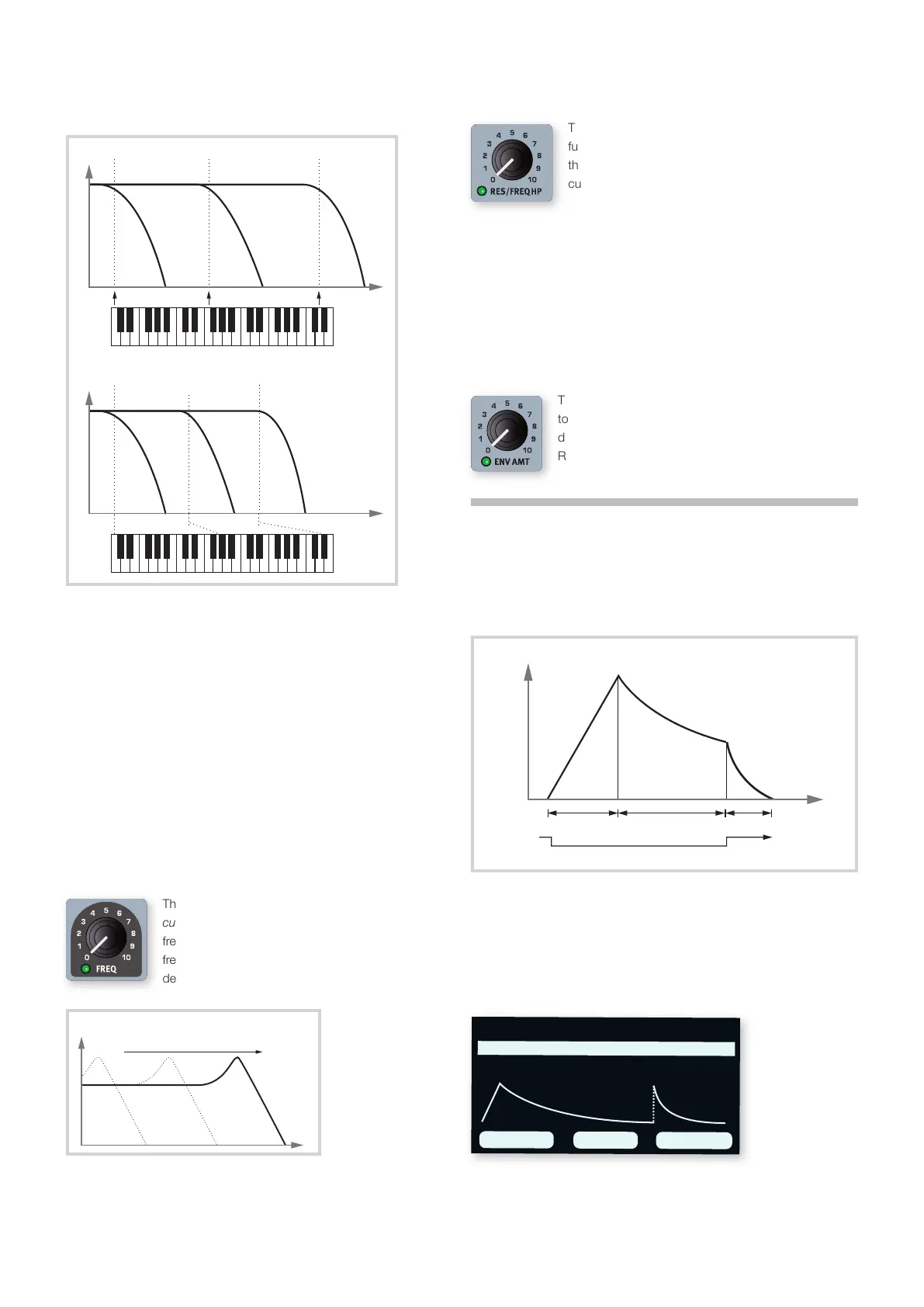
The diagrams below illustrate the relationship between keyboard
position and cut-off frequency at the 1:1 and 2/3 settings:
FILTER DRIVE
Activating DRIVE adds distortion to the Filter stage. The 1, 2 and 3
settings represent low, medium and high amounts of drive respectively.
l Using Drive with high Filter Resonance settings can yield interesting
and fun results.
GROUP
Pressing GROUP (Shift+Type) applies the current Filter settings to all
Synth Layers and keeps further edits in sync between them.
FILTER FREQUENCY
The morphable filter FREQ knob is used for setting the
cut-off frequency point – that is where in the
frequency range the filter begins to process
frequencies. The actual result of this processing
depends on the type of filter used.
The image above illustrates three different Filter Frequency settings using
a low pass filter. The area to the left of the downward slope indicates
frequencies that pass through the filter. The area to the right of the slope
are those frequencies that are reduced. The “humps” at the top indicate
a resonance setting.
FILTER RESONANCE
The morphable Resonance (RES) parameter is used to
further adjust the characteristics of the filter. Increasing
the Resonance will emphasize frequencies around the
cutoff frequency, making the sound thinner.
Further raising the Resonance will make the sound
resonant to a point where the filter starts to self-oscillate and produce
a ringing pitch. Exactly where in the frequency spectrum this “ringing”
occurs, depends on the Frequency value.
When the LP+HP filter setting is used the RES knob instead controls the
high-pass cut-off frequency, as indicated by the FREQ HP text.
ENV AMT (ENVELOPE AMOUNT)
The ENV AMT knob governs the amount of modulation
to the filter frequency by the filter envelope, which
determines how the filter frequency is altered over time.
Read more about the Filter Envelope further down.
THE ENVELOPES
The envelopes are used for shaping the sound over time, from when you
first play a key to after it has been released. The diagram below
illustrates the role of each parameter - attack, decay and release -
throughout the course of the total envelope time.
The Synth section has three separate envelopes, each accessed by
pressing the ENVELOPE button in the OSCILLATORS, FILTER and AMP
areas respectively. Read more about each envelope below.
All envelopes are visualized by the Synth display, and the three dials
below it are used for setting the Attack, Decay and Release times
respectively.
ATTACK, DECAY AND RELEASE TIMES
All envelopes have their own settings for Attack, Decay and Release
times, and the principles for how they work is the same in all instances:
freq
gain
1:1 Tracking
freq
gain
2/3 Tracking
filter frequency
freq
gain
decay (time) release (time)
key down
key up
attack (time)
time
amount
103 ms 11 s 545 ms
Pure Saw
ATTACK DECAY
RELEASE
AMP ENVELOPE
Bekijk gratis de handleiding van Nord Stage 4, stel vragen en lees de antwoorden op veelvoorkomende problemen, of gebruik onze assistent om sneller informatie in de handleiding te vinden of uitleg te krijgen over specifieke functies.
Productinformatie
| Merk | Nord |
| Model | Stage 4 |
| Categorie | Niet gecategoriseerd |
| Taal | Nederlands |
| Grootte | 10906 MB |


