Nord Modular G2 handleiding
Handleiding
Je bekijkt pagina 134 van 291
10. Technical reference: Signal types in a Patch NORD MODULAR G2 V1.4x
Page 134
10. TECHNICAL REFERENCE
SIGNAL TYPES IN A PATCH
D
EFINITIONS
Just as in a traditional analog system, modules and parameters in Nord Modular G2 interact with each
other by means of signals being connected from one place to another using a patch cable or patch cord. The
Patch cables are simply drawn with the mouse by clicking on a module output and dragging the mouse
to another module’s input while holding the mouse button down during the dragging. In a typical analog
system, the signals running through the patch cables are represented by alternating voltages ranging from
e.g. -10 to +10 volts. The signal levels in the Nord Modular G2 system are instead represented by
UNITS
,
where a value of +1 unit corresponds to a half note upwards transposition on a Pitch input on a module.
These units have nothing to do with the internal resolution of the Nord Modular G2 system, which is 24-bit, but units are
used to easily indicate signal levels in the system. The Nord Modular G2 uses three types of signals in its Patches:
• bipolar signals (-64 to +64 units)
• unipolar signals (0 to +64 units or sometimes 0 to -64 units)
• logic or gate signals (either 0 units for
LOW
or +64 units for
HIGH
)
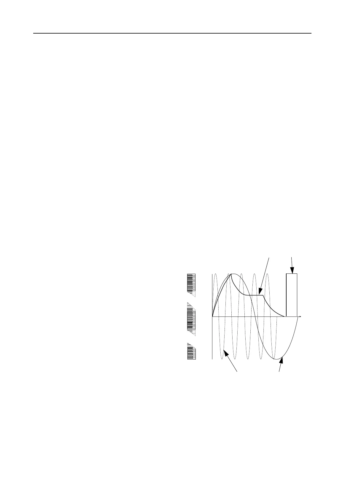
The illustration to the right shows the levels and the
polarity of the signals from the keyboard, an LFO,
an envelope, an audio signal and a logic signal.
The LFO signal in the illustration is an example of a
bipolar modulation signal. Musically this means that
this LFO signal can make an Oscillator pitch swing
higher and lower around its default pitch setting.
Note that the G2 keyboard also produces a bipolar
signal. The key E4 (
MIDI
note number 64) represents
0 units in the Nord Modular G2 system and each
increment of 1 unit means a pitch increment of a half
note up the keyboard, and a decrement of 1 unit
plays a half note down.
Envelope generators typically produce a unipolar
signal to control a loudness contour. This is logical
as volume is only positive, there is no such thing as
negative volume or ‘anti-volume’ in nature. So, an
envelope signal will typically only modulate in one direction. However, on the G2 envelope generators,
the envelope control signal output can be set to either unipolar, negative unipolar or bipolar with a scroll
button. For the simple reason that envelope control signals are used to modulate more than just a
loudness contour, e.g. sweep a filter.
0
+64
-64
units
time
E4
C-1
G9
Envelope (unipolar) Logic
Audio (bipolar) LFO (bipolar)
Bekijk gratis de handleiding van Nord Modular G2, stel vragen en lees de antwoorden op veelvoorkomende problemen, of gebruik onze assistent om sneller informatie in de handleiding te vinden of uitleg te krijgen over specifieke functies.
Productinformatie
| Merk | Nord |
| Model | Modular G2 |
| Categorie | Niet gecategoriseerd |
| Taal | Nederlands |
| Grootte | 60689 MB |


