MSW -PTROW90 handleiding
Handleiding
Je bekijkt pagina 8 van 31
14 15
Rev. 27.06.2022
Rev. 27.06.2022
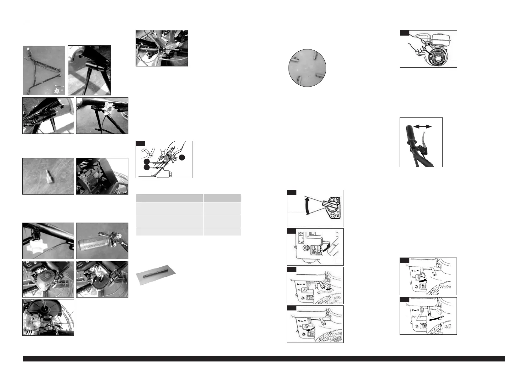
▪ Trowel blades are essential parts of the machine.
They should be replaced when they do not smooth
the concrete in a satisfactory way.
» Trowel pan
3.2. DEVICE USE
Starting the engine:
1. Turn ON/OFF switch clockwise to the “I” (ON) position
(Fig II)
2. Open the fuel valve (move to the right to the “OPEN-I”
position (Fig. III)
3. Move the speed control lever from 1/3 to 1/2 of the
high speed position distance (Fig. IV).
4. Close the suction lever (push to the far left).
CAUTION! If the engine is warm or the ambient
temperature is high, open the suction lever halfway
or leave it entirely open. If the engine is cold and the
ambient temperature is low, close the suction lever
completely (Fig. V).
5. Slowly pull the starter cable handle until you feel
resistance. This is the “compression” point. Return the
handle to its original position, then quickly pull again.
Do not pull it fully. After starting the engine and still
holding the handle, let the starter cable slowly return to
its original position. (Fig. VI)
III
OPEN
"I"
"0"
CLOSE
II
"I" (ON)
"0" (OFF)
IV
VI
Operation of the clutch lever:
1. The trowel assembly of the machine stops rotating
after the clutch lever is released. The clutch operation
should be tested every time the machine is started.
NOTE: The machine should not be left unused for
a longer time with the engine running at high speed.
This will wear or damage the belt. Set the engine
rotation at idle speed when the clutch (manual lever)
is in the o position.
Blade pitch knob
1. The knob controlling the inclination of the trowel
assembly is a large star-shaped knob at the end of
the main tube of the handle.
2. The pitch can be controlled by turning the knob.
Turning clockwise increases the pitch of the
trowel assembly while turning counter-clockwise
decreases it.
Operating the speed lever:
1. As the engine heats up, gradually move the suction
lever to the far right – open position (Fig. VII).
2. Vigorously move the speed control lever to the right,
from the LOW position (turtle) to the HIGH position
(rabbit). As soon as the motor speed reaches approx.
2300-2600 rpm, the centrifugal coupling is engaged.
(Fig. VIII, IX)
VII
ON OFF
Temperature Oil type
+120˚F ~40˚F (49˚C~4,5˚C)
(Spring, summer, autumn)
SAE 30
+40˚F ~+15˚F (4,5˚C~-9,5˚C)
(Winter)
SAE 20
Below +15˚F (-9,5˚C) SAE 10W-30
Before starting operation:
• Make sure that all impurities, blockages, unnecessary
nuts and caps, etc. have been removed from the
device. Particular attention should be paid to surfaces
that have contact with the vibrating plate and area
adjacent to the engine air intake, carburettor and air
lter.
• Check if all bolts and screws are installed and
adequately tightened. Loose bolts and screws may
damage the device.
• Check if the V-belt is properly tightened.
• Check an engine oil level (A- maximum, B- minimum).
If the level is low, top it up through the hole for the
oil dipstick(C) (Fig. I).
Use proper engine oil according to instructions in the table
below.
• Use only petrol (92% and above). When lling the fuel
tank, make sure that the fuel lter is installed.
• The device can be used with either the blades or the
pan installed on the trowel assembly:
» Trowel blades
▪ Replacing the trowel blades
If not all of the blades are replaced , the device may
go into unexpected vibrations during operation and
start wobbling or bouncing. It is recommended to
replace all the blades at the same time. To replace
the blades, place the machine on a at and level
surface. Adjust the pitch of the blades so they are
positioned as at as possible. Record the position /
setting of the blades. Undo the screws on the blade
arm, remove the blade. Then remove any impurities
(e.g. residual concrete) from the arm and install the
new blade. Mind the direction of rotation. Tighten
the screws again. Repeat this for each blade.
I
C
A
B
5. Connect the cable connector in the correct position
on the engine, then insert the engine oil sensor cable
(1) and the engine stop switch cable (2) into the
connector.
6. Guide the throttle cable through the tube on the grip
and secure the throttle lever in the proper place on
the grip. Remove the air lter from the engine, attach
the throttle cable to positions 1 and 2 and ret the
air lter.
7. Attach the engine switch cable and throttle cable in
the correct place (1) with a plastic band..
4. Undo the fastening screw from the grip handle,
attach the handle to the grip tube and tighten the
fastening screw.
EN EN
V
▪ The round plate mounted
on the trowel assembly
makes it possible to smooth
out wet concrete. The
plate design allows easy
movement from wet area to
dry area.
VIII
Bekijk gratis de handleiding van MSW -PTROW90, stel vragen en lees de antwoorden op veelvoorkomende problemen, of gebruik onze assistent om sneller informatie in de handleiding te vinden of uitleg te krijgen over specifieke functies.
Productinformatie
| Merk | MSW |
| Model | -PTROW90 |
| Categorie | Niet gecategoriseerd |
| Taal | Nederlands |
| Grootte | 11004 MB |


