Microchip MPF200TL handleiding
Handleiding
Je bekijkt pagina 38 van 102
AC Switching Characteriscs
Data Sheet
© 2024 Microchip Technology Inc. and its subsidiaries
DS00003831E - 38
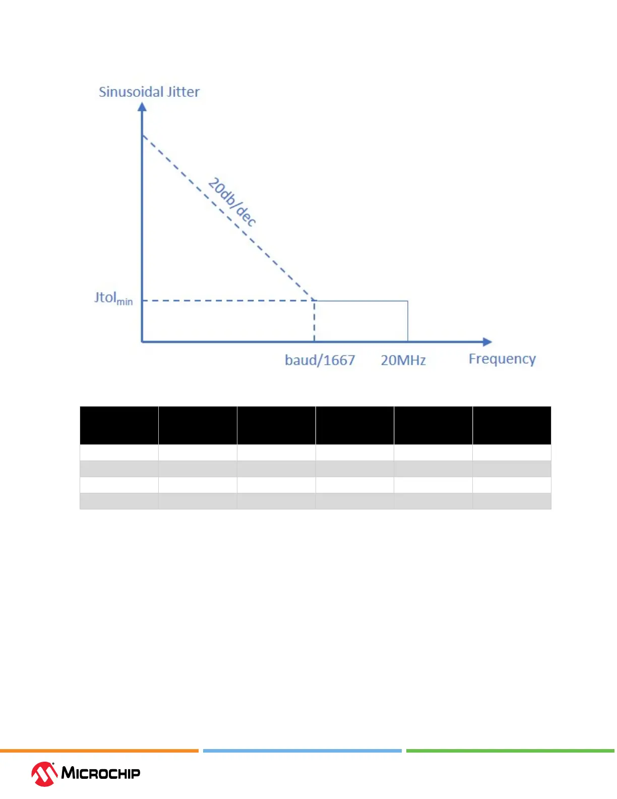
Figure 5-3. LVDS Jier Tolerance Plot
Table 5-14. I/O CDR Switching Characteriscs
Buer Type I/O Conguration Min Data Rate
(Mbps)
Max Data Rate
(Mbps)
Max Tx to Rx
Frequency Oset
(ppm)
Jtol
min
(UI)
HSIO
1, 2
LVDS18 266 1250 ±200 0.08
HSIO
1, 2
LVDS18 266 1250 ±100 0.1
GPIO
1, 3
LVDS25 266 1250 ±100 0.1
GPIO
1, 3
LVDS18G 266 1250 ±100 0.1
1. Jitter tolerance of applied sinusoidal jitter from 1 KHz to 120 MHz, as shown in Figure 5-3. LVDS
Jitter Tolerance Plot. It is measured in addition to a stressed eye of T
j
= 0.24 UI with V
ICM
of 1.25V
and V
IDmin
of 250 mV, with the CDR operating at a rate of 1250 Mbps plus or minus the ppm
oset listed.
2. HSIO LVDS uses an external 100Ω dierential termination resistor. For more information, see
LVDS specication in Table 4-17. Dierential DC Input Levels.
3. GPIO LVDS uses an internal 100Ω dierential termination resistor. For more information, see
LVDS specication in Table 4-17. Dierential DC Input Levels.
5.2 Clocking Specicaons
This section describes the PLL and DLL clocking and oscillator specications.
5.2.1 Clocking
The following table describes clocking specications.
–STD speed grade is oered for Extended Commercial (E), Industrial (I), Military (M), and Automotive
(T2) temperature grades.
Bekijk gratis de handleiding van Microchip MPF200TL, stel vragen en lees de antwoorden op veelvoorkomende problemen, of gebruik onze assistent om sneller informatie in de handleiding te vinden of uitleg te krijgen over specifieke functies.
Productinformatie
| Merk | Microchip |
| Model | MPF200TL |
| Categorie | Niet gecategoriseerd |
| Taal | Nederlands |
| Grootte | 18409 MB |


