MGL Avionics Vega TP-3 handleiding
Handleiding
Je bekijkt pagina 24 van 28
Vega TP-3 Operating Manual Page 24
10.8 Cable connections
Main connector (D15HD connector: Unit Female, Cable Male)
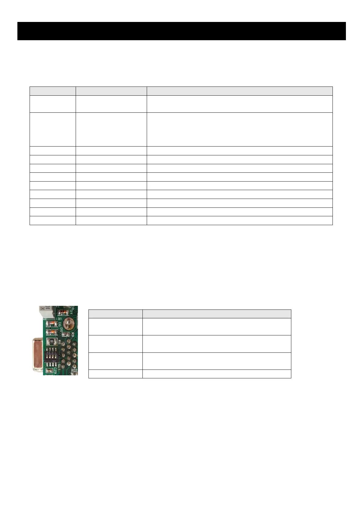
10.9 Dipswitch settings
Use a small screwdriver to change the switch direction.
D15HD Pin Color Function
1 Red 8-30Vdc power via power switch / circuit breaker
and fuse.
2 Black Ground. Connect the ground to the engine block,
and the engine block to the battery negative. Do
not connect the TP-3 ground directly to the battery
negative. This must be routed via the engine block.
3 - RS232 Transmit data (Firmware upgrading)
4 - RS232 Receive data (Firmware upgrading)
5 Green Analog Input 2
7 Orange Analog Input 1
9 Red/Yellow Stripe Analog Input 4
10 Grey Analog Input 3
12 Purple CAN Low (Used for optional external RDAC)
13 Pink CAN High (Used for optional external RDAC)
15 White Alarm Output (Open collector)
Dipswitch Function
1 Analog Input Channel 1 Pull up resistor
(On=Enable, OFF=Disable)
2 Analog Input Channel 2 Pull up resistor
(On=Enable, OFF=Disable)
3 Analog Input Channel 3 Pull up resistor
(On=Enable, OFF=Disable)
4 Not used
Bekijk gratis de handleiding van MGL Avionics Vega TP-3, stel vragen en lees de antwoorden op veelvoorkomende problemen, of gebruik onze assistent om sneller informatie in de handleiding te vinden of uitleg te krijgen over specifieke functies.
Productinformatie
| Merk | MGL Avionics |
| Model | Vega TP-3 |
| Categorie | Niet gecategoriseerd |
| Taal | Nederlands |
| Grootte | 4659 MB |
