MGL Avionics Vega TP-3 handleiding
Handleiding
Je bekijkt pagina 22 van 28
Vega TP-3 Operating Manual Page 22
10.3 Senders that are grounded in the engine block
Single wire senders require that their mounting arrangement (thread) has a very good electrical contact with the engine
block. Avoid the use of any sealant or tapes as these may cause a bad electrical connection. Further to this it is very
important that the engine block has a good electrical connection to the negative supply terminal of the TP-3. Any voltage
drop caused by other equipment on the ground wire will cause incorrect readings. The best way to ensure a good
connection is to wire a single connection between the TP-3 ground terminal (any of these terminals) and the engine block.
Do not wire this anywhere else and do not allow any other equipment to use this wire as a current return path.
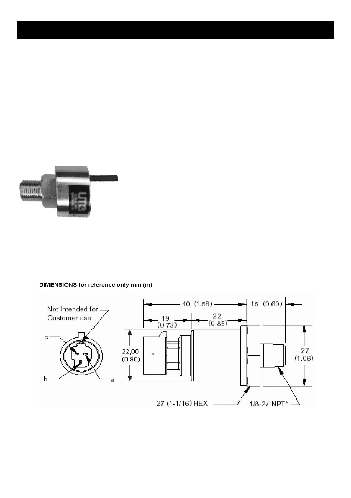
10.4 UMA Voltage output pressure sender
Pinout:
White/Orange: +12Vdc
White: Signal
White/Blue: Ground
Shield: Ground
10.5 ROTAX 912/914 4-20mA Pressure sender
The sensor cable is approximately 3m long and has 3 leads. The black lead is not to be connected and has no function.
The Red lead from the sensor has to be connected to the positive bus via a fuse or circuit breaker . The white lead
(Output signal) has to be connected directly to the TP-3 analog input channel. The supplied 100Ohm 1/4W resistor must
be connected across the analog input channel to ground. The internal pull up resistor dip switch for the 4-20mA current
sender input must be in the “OFF” position.
Bekijk gratis de handleiding van MGL Avionics Vega TP-3, stel vragen en lees de antwoorden op veelvoorkomende problemen, of gebruik onze assistent om sneller informatie in de handleiding te vinden of uitleg te krijgen over specifieke functies.
Productinformatie
| Merk | MGL Avionics |
| Model | Vega TP-3 |
| Categorie | Niet gecategoriseerd |
| Taal | Nederlands |
| Grootte | 4659 MB |
