Marshall Electronics RCP-PLUS handleiding
Handleiding
Je bekijkt pagina 4 van 8
5 6
RCP-PLUS User Manual
Step 1. Press VISCA over RS485. The camera add page appears.
Step 2. Press Select Camera Model
Step 3. Select the camera model number that most closely matches
the Marshall camera that is connected.
For example: select CV36*/CV56* when using a CV368.
Note: Selecting Universal is only recommended for 3rd party products.
The RCP-PLUS can control only functions that exist in the attached camera
even though that function may appear as a choice on the display.
Step 4. The RCP-PLUSassignstherstcamera“Label”as 1. If the
camerawillbereferredtoassomeothernumberduringliveproduction,
the label on the button may be changed to a number or letter as desired. Press RCP Label,turnthe
leftknobclockwisefornumbers,counterclockwiseforletters.Chooseone.Next,pressCamera ID,turn
the right knob to set the ID number to match the ID number that is set in the camera. With Visca, each
camera much have a unique ID number from 1 – 7.
Step 5. Press Select Output Format to set the desired camera output format and Frame Rate by making
selections on the next page.
Step 6. Press Apply to make these changes active. The display will change to the White Balance page
(WB is highlighted) and is ready for use.
Step 7. Assumingthecameraisconnectedandpowered,aquickcheckcanbeperformedbypressing
the OSDbutton,thenpressOn. The camera’s on-screen menus should appear in the camera’s video
output. Press On again once or twice to clear the menu display.
Ifthisquickcheckworked,normaloperationcanbeginbyselectingthedesiredfunctionfromtheright
sideofthescreen(WhiteBalance,Exposure,etc.). If the quick check did not work, check all connections,
try having only one camera connected, check that the Visca ID # in the RCP-PLUS and the camera are
the same, and try swapping + and – at one end of the cable.
3.1 Wiring
Use either the included 3-pin XLR to 2-pin terminal adapter cable or build a cable using a 3-pin XLR
plug. RS485 needs only two wires to communicate. For tips on wiring for RS485, see chapter 8.
3.2 Power Up
Connect the included 12V Power Supply or Ethernet with PoE to the RCP-PLUS. The unit will display the
main page after approximately 10 seconds. There are 10 buttons available for camera assignment
in this Group. This may be all that is needed when using RS485 connections. (Visca protocol is
limited to 7 cameras). IP connectivity allows up to 100 cameras in 10 pages (see Section 4 below).
3.3 Assigning a Camera to a button.
Theupperleftbuttonwillbehighlighted.Ifnot,pressandholdablankbuttonfor3secondsandrelease.
Chapter 3: Assigning Cameras via RS485
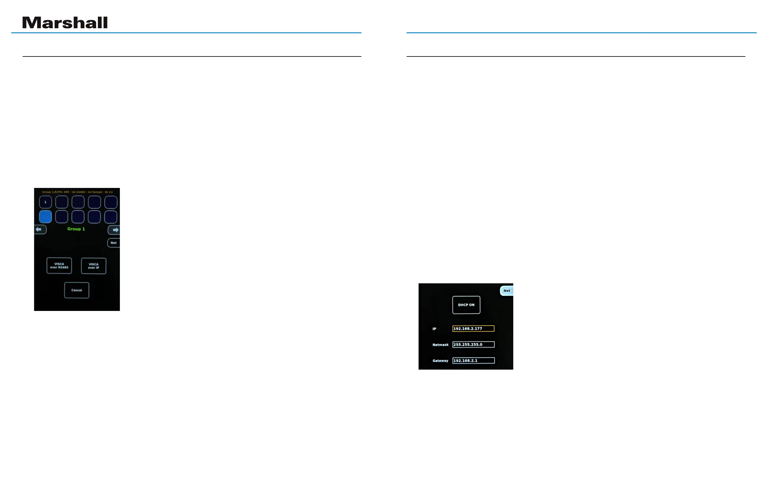
Choose DHCP or Static Address
Setting DHCP mode (Automatic IP Address)
TocontrolcamerasviaIP,itisnecessarytorstconnecttheRCP-PLUS to the local network. This means
assigninganIPaddress,SubnetMaskandGateway.IfaStaticaddressisnotrequired,thenitisasimple
processofplacingthecontrollerinDHCP(automaticaddress)mode,connectingitphysicallyviaaCAT5or6
cable to the network and moving on to section
4.1 Connecting Cameras via IP.
ToplacetheRCP-PLUSinDHCPmode,taponanyblanksquarethentaponNet.NowtapontheDHCPbutton
inthemiddleofthescreensothatitsaysDHCPON,thenTapNetagain.
Static Address
If it is desired to assign a Static IP address to the RCP-PLUS controller, this can be accomplished in
either of two ways:
- Through the RCP-PLUS touch screen. This method would be chosen if it is not possible to access a
computer that is on the local network. Setting a network address via the touch screen will require knob
turning,buttontappingandsomepatience.
- Through a web browser. Ifanetworkcomputerisavailable,thismethodisquickerasaddressnumbers
may simply be typed.
TousetheWebBrowser,jumptosection5.WebBrowserSetup.
Tousethetouchscreen,continuewiththestepsbelow.
Onthetouchscreen,tapanyblanksquare,tapNet,thentaptheDHCP button so that it says DHCP OFF.
This will cause the IP address box to have a highlighted border and the
default address of192.168.2.177 will appear there. (If a Static address has
beensetpreviously,thataddresswillappearinstead).
The address may be changed by following this step-by-step process:
Step 1. Press down on the Right Knob. An arrow will appear to the left of
theaddressindicatingthattherstpartoftheaddressistobechanged.If
thispartoftheaddressisOK(forexample192),turntheRightKnobuntilthe
arrow is pointing to the portion of the address that needs to be changed.
Step 2. Turn the Left Knob until the desired number appears. Turn the Right Knob again to move the arrow
tothenext3digits.Whenthedesiredaddresshasbeenentered,pressdownontheRightKnobtocomplete
the process. This is indicated by the numbers turning white and the border around the numbers being
highlighted with a color.
Step 3. Now,turntheRightKnobagaintoselectNetmask or Gateway. Repeat the process above to enter
new values into those boxes. Press Netagaintonish.ThissetsthenewStaticaddressastheDefaultaddress.
Chapter 4: Connecting RCP to a Network
Bekijk gratis de handleiding van Marshall Electronics RCP-PLUS, stel vragen en lees de antwoorden op veelvoorkomende problemen, of gebruik onze assistent om sneller informatie in de handleiding te vinden of uitleg te krijgen over specifieke functies.
Productinformatie
| Merk | Marshall Electronics |
| Model | RCP-PLUS |
| Categorie | Niet gecategoriseerd |
| Taal | Nederlands |
| Grootte | 3905 MB |
