Lutron Caseta DVRF-6L-WH handleiding
Handleiding
Je bekijkt pagina 18 van 30
®
SPECIFICATION SUBMITTAL Page
Job Name:
Job Number:
Model Numbers:
Caséta by Lutron Load Controls
369987l 18 2.24.23
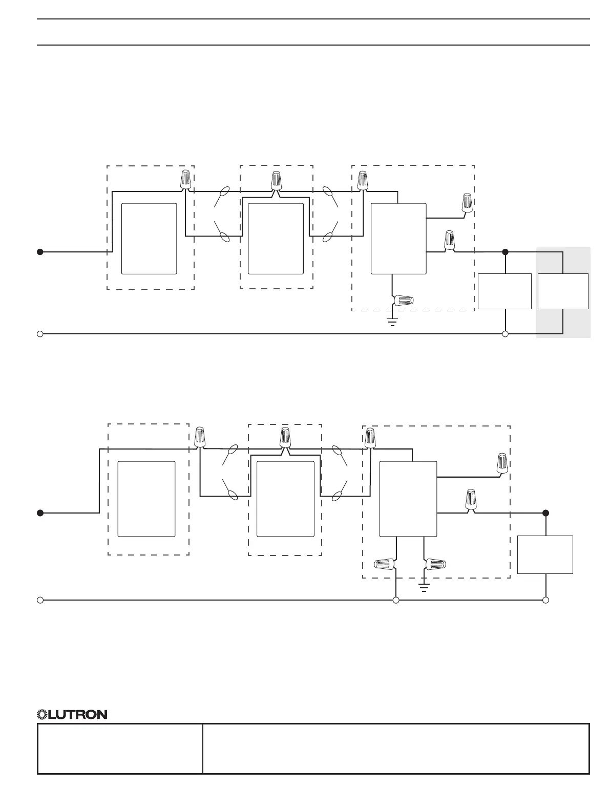
Wiring Diagrams - Switches (continued)
1
When using controls without mechanical 3-way switch, cap the blue terminal. Do not connect the blue wire to any other wiring or to ground.
2
A LUT-MLC ensures proper function when LED, fluorescent, or ELV loads are used. Install the LUT-MLC inside a load fixture or in a separate junction box
within the circuit.
3
The mechanical switch will need to be removed so the Pico remote control can be installed.
4
The red wire must be connected to the load and the black wire must be connected to Line / Hot. The switch will not work if the wires are reversed.
Multi-location Installation (load is controlled from 3 or more locations)
Option 1: With Pico remote controls
PJ2-2B-xx and wallbox mounting adapters (PICO-WBX-ADAPT)
Pico
Remote
Control and
Wallbox
Mounting
Adapter
3
Pico
Remote
Control and
Wallbox
Mounting
Adapter
3
Pico
Remote
Control and
Wallbox
Mounting
Adapter
3
Pico
Remote
Control and
Wallbox
Mounting
Adapter
3
PD-5ANS,
PD-6ANS
or DVRF-5NS
PD-5WS-DV
LUT-MLC
2
Load
Load
Line / Hot
Line / Hot
Neutral
Neutral
GreenWhite
Green
Ground
Ground
Red
4
Red
Black
Black
Black
Black
Blue
1
Blue
1
120 V~
50 / 60 Hz
120 / 277 V~
50 / 60 Hz
Travelers
Travelers
Travelers
Travelers
PD-5WS-DV
PD-5ANS, PD-6ANS, DVRF-5NS
Location 1 Location 2 Location 3
Location 1 Location 2
Location 3
18
Bekijk gratis de handleiding van Lutron Caseta DVRF-6L-WH, stel vragen en lees de antwoorden op veelvoorkomende problemen, of gebruik onze assistent om sneller informatie in de handleiding te vinden of uitleg te krijgen over specifieke functies.
Productinformatie
| Merk | Lutron |
| Model | Caseta DVRF-6L-WH |
| Categorie | Niet gecategoriseerd |
| Taal | Nederlands |
| Grootte | 3733 MB |

