Liberty Pumps XLSGX200 handleiding
Handleiding
Je bekijkt pagina 5 van 12
6850000E Copyright © Liberty Pumps, Inc. 2022
All rights reserved. 5 | EN
Pump System Components
Control Panel
Float switches must be connected to an intrinsically safe
circuit in the control panel as per the requirements of
Chapter
5 of the National Electric Code®.
XLSG/XLSGX-Series grinder pumps require a separate, approved
control panel for automatic operation. Operation will be according
to the control selected. Refer to separate manufacturer’s
instructions supplied with the unit.
The control panel shall be installed outside the hazardous area and
appropriately isolated and sealed to prevent any potential ignition
or explosion. Only approved controls that have intrinsically safe
float switch connections shall be used. Mounting, installation and
wiring connections are specific to the control panel used. Refer to
the manufacturer’s instructions supplied with the unit.
IMPORTANT: When connecting an XLSG/XLSGX-Series pump to
an existing control panel, verify the panel is correctly sized and
equipped for the pump.
The control panel for 3-phase pumps shall have provisions for the
thermostats that open the motor contactors in order to maintain
the T4 (135°C) temperature class. Do not exceed voltage/current
combinations for the thermostat: 16
VDC/20 Amps, 115 VAC/
22
Amps, 277 VAC/8 Amps, 600 VAC/4 Amps. All models have a
temperature (T) class rating of T4 with thermostats connected.
Failure to use the proper circuitry and to connect the thermostat
will void the T4 temperature class of the pump and will drop the
temperature class to T3 (200°C).
Intrinsically safe control panels designed for use with the XLSG/
XLSGX-Series pumps available from Liberty Pumps can be found at
www.LibertyPumps.com/Portals/0/Files/panel_selection_guide.pdf
or contact Liberty Pumps.
1-phase pumps require a panel-mounted start circuit consisting of
a start capacitor, run capacitor, and start relay, which are available
separately. Refer to
Table 1 for these control panel components.
Overload Protection
XLSG/XLSGX-Series grinder pumps require overload protection in
the control panel. The motor control unit shall be approved and
shall be properly sized or adjusted for the full load input power
indicated on the pump nameplate. It is important to properly
adjust or select the motor control overload protection. The full
load amps on the nameplate should be used as a baseline, but it is
important to consider that events such as supply voltage variation
or large solids passing through the pump can temporarily increase
current draw. To avoid possible nuisance tripping, it may be
necessary to adjust overloads to a value slightly higher than the full
load input power indicated on the pump nameplate.
Seal Failure Probes
XLSG/XLSGX-Series grinder pumps are equipped with two
mechanical face seals with an intermediate oil chamber between
them. This ensures lubrication for the seals, shaft flame path, and
as a barrier to the motor chamber in the event the lower seal is
compromised. A seal fail or moisture sensing device is located in
the mid oil chamber and continuously monitors for leakage. In the
event of a seal failure, moisture mixes with the oil, tripping the seal
leak circuit. In a failure condition, a fault light will illuminate on the
control panel. The pump will continue to operate, but service
should be scheduled as soon as possible.
Intrinsically safe (ISS and ISD) control panels by Liberty Pumps
have a seal leak test button that tests the integrity of the seal leak
circuit continuity. When pressed, the light should illuminate. The
light should go off when the test button is released. If it remains
on, the potentiometer is set too high. If light does not illuminate,
the light is burned out, the circuitry is open, or the system does not
have power. The seal leak relay requires adjustment upon
installation. See Seal leak relay setup on
page 8.
Seal fail probes connect to a relay in the control panel, which is
included in a Liberty Pumps control panel. For a non-Liberty
Pumps control panel or for a replacement relay, refer to
Table 2.
Power and Control Cords
Do not remove cord and strain relief, and do not connect
conduit to pump.
The power and control cords cannot be spliced; a junction box may
be used providing it is rated for hazardous locations and has
approved cord connectors.
IMPORTANT: Each cord has a green lead. This is the ground wire
and must be grounded properly per NEC
®
and/or local codes.
RISK OF SERIOUS INJURY OR DEATH
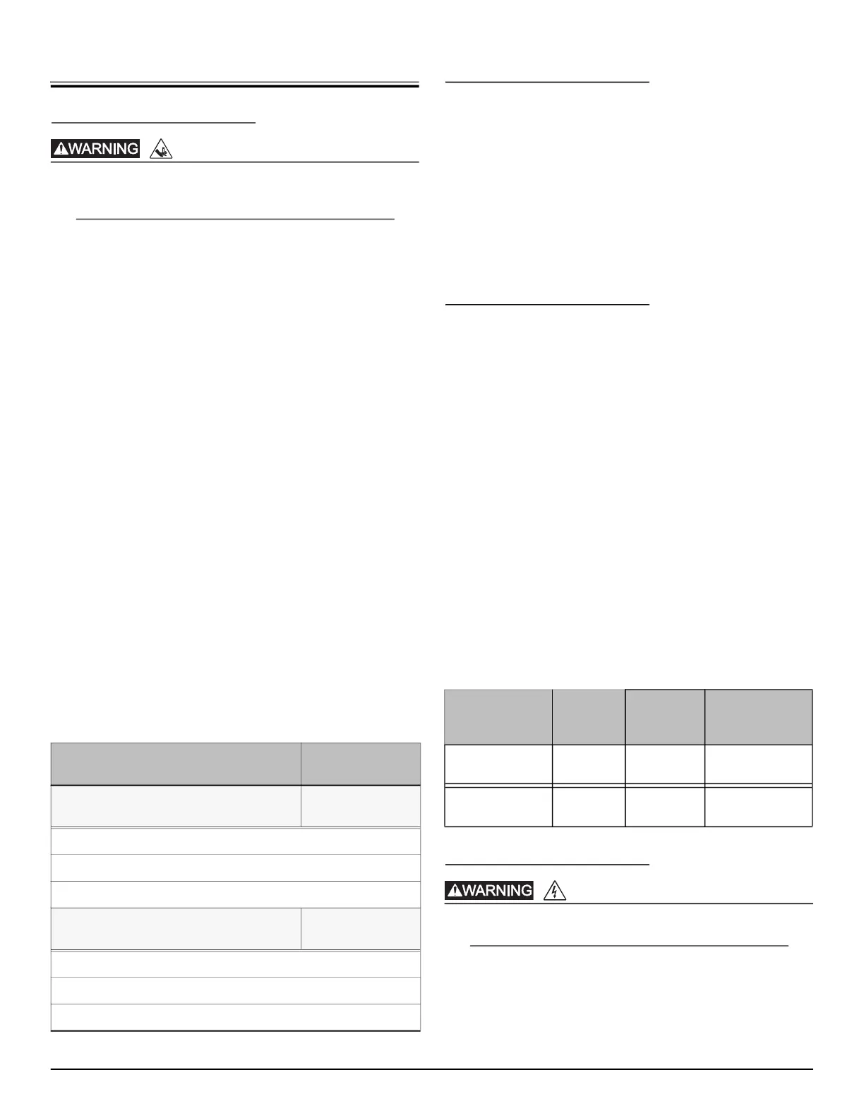
Table 1. Control Panel Components 1-Phase
Required Component and Specification
Liberty Pumps
P/N
208 V 1-phase Start Kit
(contains 3 items listed separately below)
K001640
Start Capacitor, 270–324 µF 220/250 VAC
Run Capacitor, 65 µF 370 VAC
Start Relay
230 V 1-phase Start Kit
(contains 3 items listed separately below)
K001641
Start Capacitor, 270–324 µF 220/250 VAC
Run Capacitor, 50 µF 370 VAC
Start Relay
Table 2. Seal Fail Replacement Relay
Description
Relay
Input
Voltage
Liberty
Pumps
P/N
Macromatic
P/N
Simplex, controls
1 pump
120V K001672 SFP120A250
Duplex, controls
2 pumps
120V K001675 SFP120C250
RISK OF ELECTRIC SHOCK
Bekijk gratis de handleiding van Liberty Pumps XLSGX200, stel vragen en lees de antwoorden op veelvoorkomende problemen, of gebruik onze assistent om sneller informatie in de handleiding te vinden of uitleg te krijgen over specifieke functies.
Productinformatie
| Merk | Liberty Pumps |
| Model | XLSGX200 |
| Categorie | Niet gecategoriseerd |
| Taal | Nederlands |
| Grootte | 2107 MB |


