Handleiding
Je bekijkt pagina 48 van 76
Screw specifications Number of screws
M2 x L2.8 2
M2 x L3.5 3
Go to
https://support.lenovo.com/partslookup to look up the Lenovo part numbers of the following
replacement parts:
System board
Use a Golden Key U1 tool to flash-write key id information
After replacing the system board and re-assembling the computer, use a pre-made Golden Key U1 tool to
start the computer and flash-write the serial number (SN), machine type (MT), product name (PN), and UUID
to the new system board.
The Golden Key U1 tool is prepared by running the U1 Update software on a FAT32-formatted USB thumb
drive. Go to
http://support.lenovo.com/us/en/solutions/HT506954 for detailed instructions on how to create
and use a Goldern Key U1 tool.
Remove the LCD module
Make sure the following FRUs (CRUs) have been removed.
“Remove the lower case” on page 30
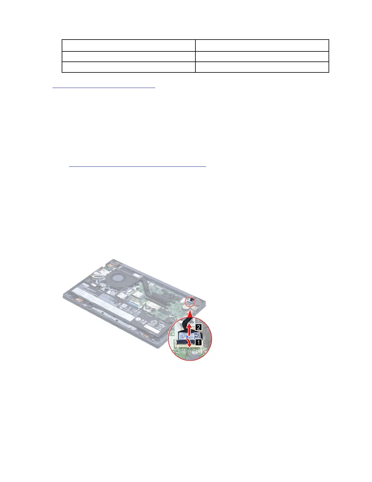
Step 1. Disconnect the battery pack cable from the system board.
Attention: Use your fingernails to pull the connector to unplug it. Do not pull the cable.
Step 2. Disconnect the EDP cable from the system board.
Figure 25. Disconnect the EDP cable from the system board
Step 3. Rotate the LCD unit to an angle of more than 90 degrees and place the computer on a flat surface
as shown. Remove four screws and then remove the LCD module.
42
Hardware Maintenance Manual
Bekijk gratis de handleiding van Lenovo V15 Gen 4, stel vragen en lees de antwoorden op veelvoorkomende problemen, of gebruik onze assistent om sneller informatie in de handleiding te vinden of uitleg te krijgen over specifieke functies.
Productinformatie
| Merk | Lenovo |
| Model | V15 Gen 4 |
| Categorie | Laptop |
| Taal | Nederlands |
| Grootte | 19204 MB |


