KStrong Wrangler UFA40010 handleiding
Handleiding
Je bekijkt pagina 3 van 8
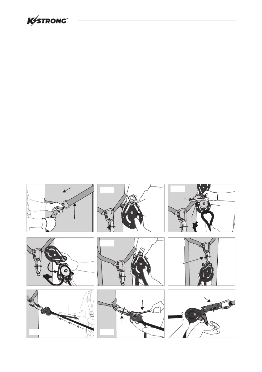
Installation of Temporary Horizontal Lifeline-
STEP 1: The receiving structure onto which lifeline is to be installed must be strong enough to hold an impact load of more
than 5000 lbs. Fig. 01
STEP 2: Installation of rope into the tensioner:
Ÿ Loosen the knob to slide open the housing cover plate. Fig. 02
Ÿ Pull back the Hockey and Lock Body so as to create adequate gap to insert rope around the pulley. Please
refer attached image for the direction of rope insertion. Fig. 03
Ÿ Slide back the cover plate and ensure that hole on cover plates match with spacer on the fixed cover plate.
Fig. 04
Ÿ Once aligned, re-tighten the knob to the fullest to hold the cover plates in position. Fig. 05
STEP 3 : With the help of a Carabiner attached to the swivel connector of lifeline, connect the rope to a suitable anchorage
point. (In case of any unavailability of anchor point use KARAM Cross Arm Strap to create one.) Fig. 01
STEP 4: Now connect the tensioner to the second anchorage point along with tension indicator by attaching a Carabiner to
the hockey eye of tension indicator. Fig. 06
STEP 5 : Pull the initial slack of rope by hand and ensure that rope is seated properly in the groove of pulley. Fig. 07
STEP 6 : Use an open end spanner of 0.944 inches provided along with tensioner to give appropriate tension to the lifeline.
Plate of Tension indicator will start to rotate freely once the required tension has been achieved in lifeline. Now, O
rings/ pass through carriages can be used as mobile anchors for the workers. Fig. 08
STEP 7 : To uninstall the lifeline, push the lock backwards in order to pull back the hockey. Hockey will release the pulley and
allow rope to loosen. Fig. 9
STEP 8 : Now lifeline may be taken off from the anchorage.
STEP 9 : After uninstallation, inspect the entire lifeline for any evidence of damage, wear, corrosion on tensioner body and
separation of rope fibers.
Fig 04
Fig 02
Knob
Housing
Cover
Plate
Fig 06
Tension
Indicator
Fig 01
Cross
Arm Strap
Structure
Fig 05
Fig 09
Indicator
Plate
Fig 08
Spanner
Indicator
Plate
Pull the Rope
for proper tension
Fig 07
Fig 03
Hockey
Lock
Pulley
2
Bekijk gratis de handleiding van KStrong Wrangler UFA40010, stel vragen en lees de antwoorden op veelvoorkomende problemen, of gebruik onze assistent om sneller informatie in de handleiding te vinden of uitleg te krijgen over specifieke functies.
Productinformatie
| Merk | KStrong |
| Model | Wrangler UFA40010 |
| Categorie | Niet gecategoriseerd |
| Taal | Nederlands |
| Grootte | 853 MB |


