Kramer VP-16x18AK handleiding
Handleiding
Je bekijkt pagina 55 van 60
Kramer Protocol
51
51
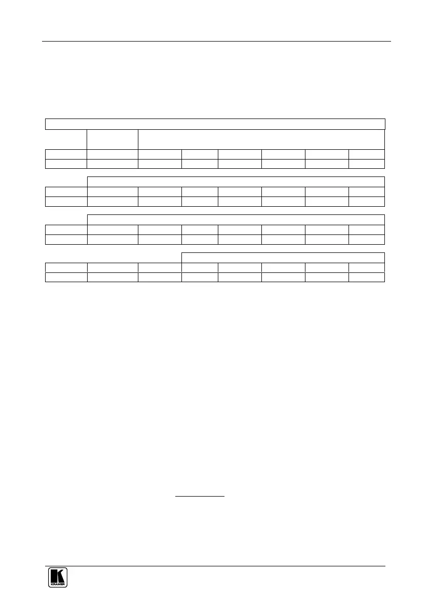
16.3 Kramer Protocol 2000
This RS-232/RS-485 communication protocol uses four bytes of
information as defined below. The default data rate is 115200 baud, with no
parity, 8 data bits and 1 stop bit.
Table 18: Protocol Definitions
MSB
LSB
DESTI-
NATION
INSTRUCTION
0
D
N5
N4
N3
N2
N1
N0
7
6
5
4
3
2
1
0
1st byte
INPUT
1
I6
I5
I4
I3
I2
I1
I0
7
6
5
4
3
2
1
0
2nd byte
OUTPUT
1
O6
O5
O4
O3
O2
O1
O0
7
6
5
4
3
2
1
0
3rd byte
MACHINE NUMBER
1
OVR
X
M4
M3
M2
M1
M0
7
6
5
4
3
2
1
0
4th byte
1
st
BYTE: Bit 7 – Defined as 0.
D – “DESTINATION”: 0 - for sending information to the switchers (from the PC);
1 - for sending to the PC (from the switcher).
N5…N0 – “INSTRUCTION”
The function that is to be performed by the switcher(s) is defined by the INSTRUCTION (6 bits). Similarly, if a function is
performed via the machine’s keyboard, then these bits are set with the INSTRUCTION NO., which was performed. The
instruction codes are defined according to the table below (INSTRUCTION NO. is the value to be set for N5…N0).
2
nd
BYTE: Bit 7 – Defined as 1.
I6…I0 – “INPUT”.
When switching (ie. instruction codes 1 and 2), the INPUT (7 bits) is set as the input number which is to be switched.
Similarly, if switching is done via the machine’s front-panel, then these bits are set with the INPUT NUMBER which was
switched. For other operations, these bits are defined according to the table.
3
rd
BYTE: Bit 7 – Defined as 1.
O6…O0 – “OUTPUT”.
When switching (ie. instruction codes 1 and 2), the OUTPUT (7 bits) is set as the output number which is to be switched.
Similarly, if switching is done via the machine’s front-panel, then these bits are set with the OUTPUT NUMBER which was
switched. For other operations, these bits are defined according to the table.
4
th
BYTE: Bit 7 – Defined as 1.
Bit 5 – Don’t care.
OVR – Machine number override.
M4…M0 – MACHINE NUMBER.
Used to address machines in a system via their machine numbers. When several machines are controlled from a single serial
port, they are usually configured together with each machine having an individual machine number. If the OVR bit is set, then
all machine numbers will accept (implement) the command, and the addressed machine will reply.
For a single machine controlled via the serial port, always set M4…M0 = 1, and make sure that the machine itself is
configured as MACHINE NUMBER = 1.
Bekijk gratis de handleiding van Kramer VP-16x18AK, stel vragen en lees de antwoorden op veelvoorkomende problemen, of gebruik onze assistent om sneller informatie in de handleiding te vinden of uitleg te krijgen over specifieke functies.
Productinformatie
| Merk | Kramer |
| Model | VP-16x18AK |
| Categorie | Niet gecategoriseerd |
| Taal | Nederlands |
| Grootte | 9636 MB |
Caratteristiche Prodotto
| Kleur van het product | Zwart |
| Gewicht | 4400 g |
| LED-indicatoren | Ja |
| AC-adapter ingangsspanning | 100 - 240 V |
| Meegeleverde kabels | AC |


