Kichler Bead handleiding
Handleiding
Je bekijkt pagina 9 van 54
54" Bead LED | 9
MAKE THE ELECTRICAL CONNECTIONS
WARNING: WARNING: To avoid possible electrical shock, be sure you have turned off To avoid possible electrical shock, be sure you have turned off
the power at the main circuit panel before wiring. Follow the steps below the power at the main circuit panel before wiring. Follow the steps below
to connect the fan to your household wiring. Use the wire connecting nuts to connect the fan to your household wiring. Use the wire connecting nuts
supplied with your fan. Secure the connector with electrical tape. Make sure supplied with your fan. Secure the connector with electrical tape. Make sure
there are no loose wire stands or connections.there are no loose wire stands or connections.
WARNING: WARNING: If your house wires are different colors than referenced in this If your house wires are different colors than referenced in this
manual, stop immediately. A professional electrician is recommended to manual, stop immediately. A professional electrician is recommended to
determine proper wiring.determine proper wiring.
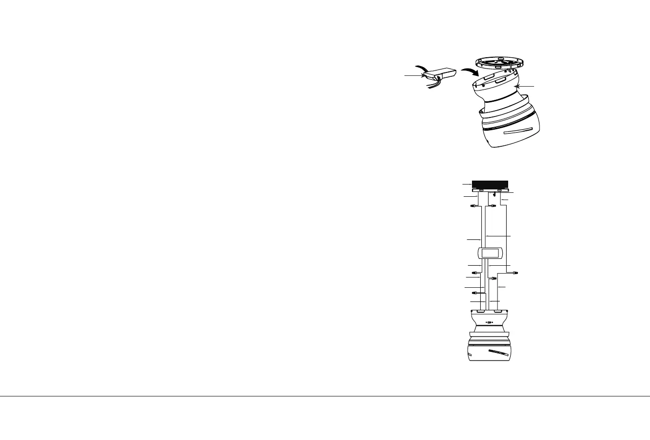
Step 1. Step 1. Insert the receiver into the motor assembly, and keep flat in opposition Insert the receiver into the motor assembly, and keep flat in opposition
of ceiling. (Fig. 9)of ceiling. (Fig. 9)
Step 2.Step 2. Motor to Receiver Electrical Connections: Connect the BLACK Motor to Receiver Electrical Connections: Connect the BLACK
wire from the fan to BLACK wire marked "TO MOTOR L" from the receiver. wire from the fan to BLACK wire marked "TO MOTOR L" from the receiver.
Connect the WHITE wire from the fan to the WHITE wire marked "TO MOTOR Connect the WHITE wire from the fan to the WHITE wire marked "TO MOTOR
N" from the receiver. Connect the BLUE wire from the fan to the BLUE wire N" from the receiver. Connect the BLUE wire from the fan to the BLUE wire
marked "FOR LIGHT" from the receiver. Secure all the wire connections with marked "FOR LIGHT" from the receiver. Secure all the wire connections with
the plastic wire connectors provided. (Fig. 10)the plastic wire connectors provided. (Fig. 10)
Step 3. Step 3. Remote Receiver to Outlet Box Electrical Connections: Connect the Remote Receiver to Outlet Box Electrical Connections: Connect the
BLACK (hot) wire from the ceiling to the BLACK wire marked "AC IN L" from BLACK (hot) wire from the ceiling to the BLACK wire marked "AC IN L" from
the receiver. Connect the WHITE (Neutral) wire from the ceiling to the WHITE the receiver. Connect the WHITE (Neutral) wire from the ceiling to the WHITE
wire marked "AC IN N" from the receiver. Secure all the wire connections with wire marked "AC IN N" from the receiver. Secure all the wire connections with
the plastic wire connectors provided. (Fig. 10) the plastic wire connectors provided. (Fig. 10)
Receiver
Motor Assembly
Outlex box
White
Green or bare copper (ground)
White("AC IN N")
White("TO MOTOR N")
Ground wire
White(Neutral)
Black
Black("AC IN L")
Black ("TO MOTOR L"
Black (motor)
Blue(FOR LIGHT)
Blue(for light)
Fig. 9
Fig. 10
Bekijk gratis de handleiding van Kichler Bead, stel vragen en lees de antwoorden op veelvoorkomende problemen, of gebruik onze assistent om sneller informatie in de handleiding te vinden of uitleg te krijgen over specifieke functies.
Productinformatie
| Merk | Kichler |
| Model | Bead |
| Categorie | Ventilator |
| Taal | Nederlands |
| Grootte | 3931 MB |


