Handleiding
Je bekijkt pagina 53 van 112
Fitting - installing:
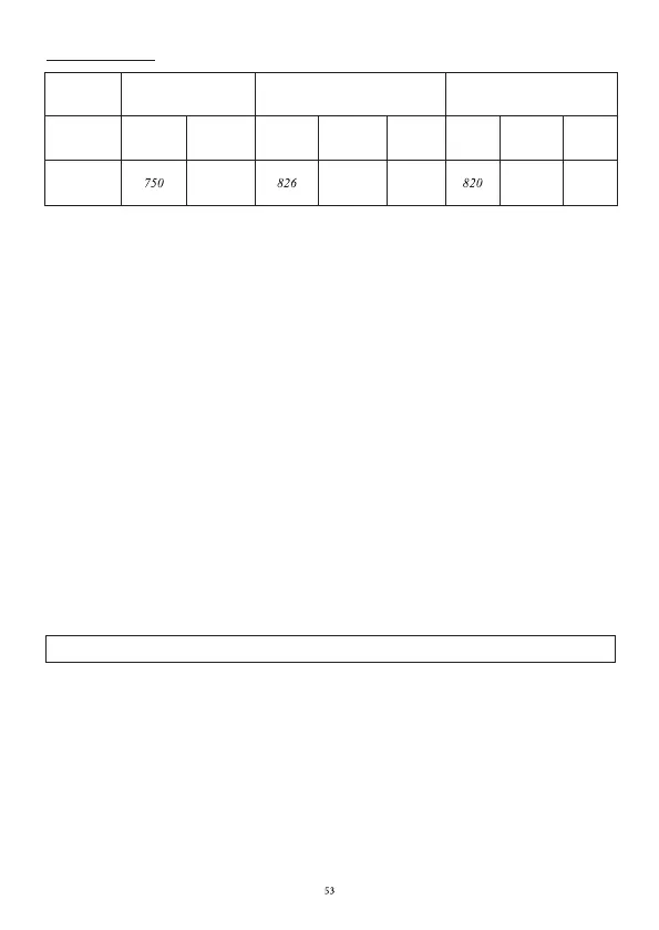
Cut size Flush mounting Glass size
Type
Width Depth Width Depth Radius
Width Depth Thickness
490 526 8 520 4
• Ensure that there is a distance of 50 mm between the hob and the wall or sides.
• The hobs are classified as “Y” class for heat protection. Ideally the hob should be installed with plenty of
space on either side. There may be a wall at the rear and tall units or a wall at one side. On the other side,
however, no unit or divider must stand higher than the hob.
• The piece of furniture or the support in which the hob is to be fitted, as well as the edges of furniture,
the laminate coatings and the glue used to fix them, must be able to resist temperatures of up to 100 °C.
• Do not install the
hob at the top of a non ventilated oven or a dishwasher.
• Ensure under the bottom of the hob casing a space of 20 mm to ensure good air circulation of the
electronic device.
• If a drawer is placed under the hob, avoid putting into this drawer flammable objects (for example:
sprays) or non heat-resistant objects.
• Materials which are often used to make worktops expand on contact with water. To protect the cut out
edge, apply a coat of varnish or special sealant. Particular care must be taken when applying the adhesive
joint supplied with the hob to prevent any leakage into the supporting furniture. This gasket
ensures a
good seal when used in conjunction with smooth work top surfaces.
• The safety gap between the hob and the cooker hood placed above must comply with the recommendations
of the hood manufacturer. In the case of no instructions, a distance of 760 mm minimum should apply.
• The connection cord should not be subjected to any mechanical constraint.
• WARNING: Use only hob guards designed by the manufacturer of the cooking appliance or
indicated by the manufacturer of the appliance in the instructions for use as suitable or hob guards
incorporated in the appliance. The use of inappropriate guards can cause accidents.
• The installation
of this appliance and the connection to the electrical network should be entrusted only
to an electrician perfectly to the fact of the normative regulations and which respects them scrupulously.
• Protection against the parts under tension must be ensured after the building-in.
• The data of connection necessary are on the stickers place on the hob casing near the connection box.
• The connection to the main must be made using an earthed plug or via an omnipolar circuit breaking
device with a contact opening of at least 3 mm.
• The electrical circuit must be separated from the network by adapted devices, for example: circuit
CHAPTER 11. ELECTRICAL CONNECTION
breakers, fuses or contactors.
• If the appliance is not fitted with an accessible plug, disconnecting means must be incorporated in the
fixed installation, in accordance with the installation regulations.
• The inlet hose must be positioned so that it does not touch any of the hot parts of the hob or oven.
KIH7534-
1-5B-BL
Bekijk gratis de handleiding van Kernau KIH 7534.1-5B-BL, stel vragen en lees de antwoorden op veelvoorkomende problemen, of gebruik onze assistent om sneller informatie in de handleiding te vinden of uitleg te krijgen over specifieke functies.
Productinformatie
| Merk | Kernau |
| Model | KIH 7534.1-5B-BL |
| Categorie | Fornuis |
| Taal | Nederlands |
| Grootte | 7418 MB |


