Jung SITMA5073 handleiding
Handleiding
Je bekijkt pagina 39 van 140
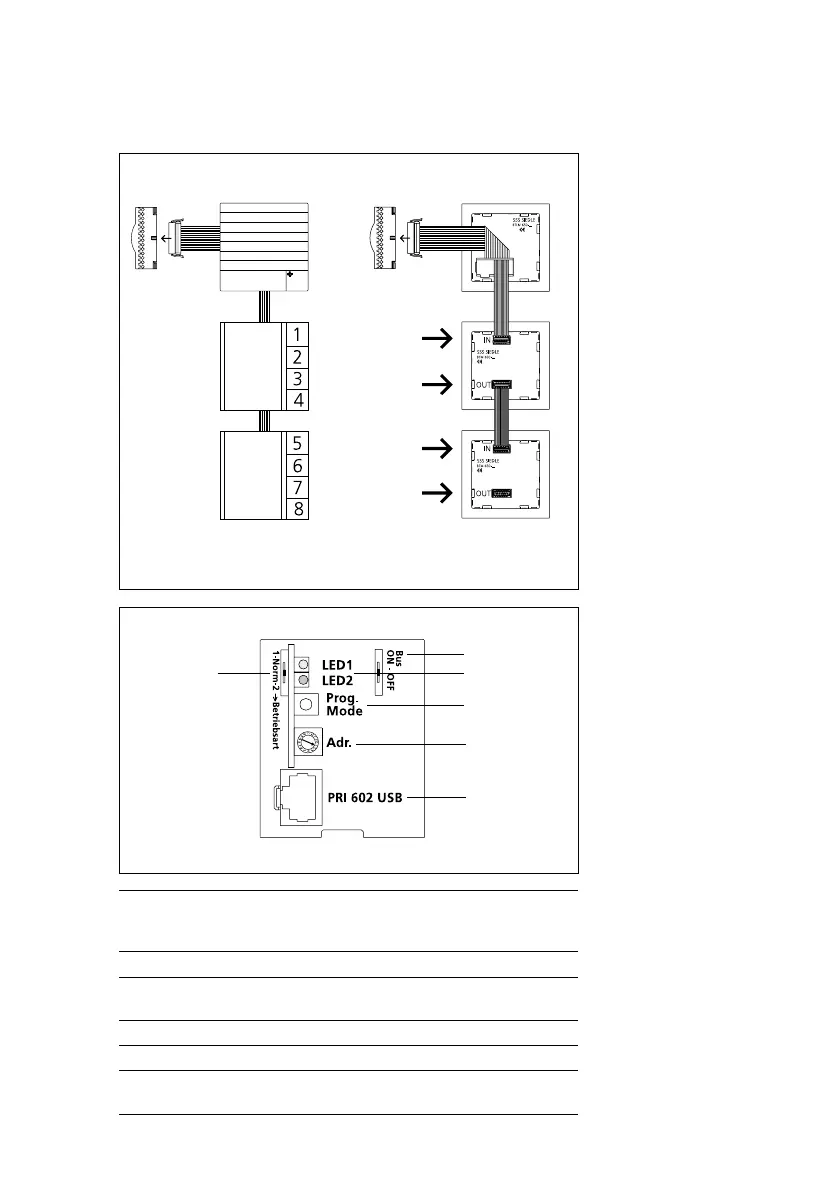
Bus call button module, bus video line rectier
BTLM 650-04
In-Home-Bus
IN
OUT
IN
OUT
up to max. 40
bus call button module
BTLM 650-04
In-Home-Bus
up to max.
160 call buttons
Bus call button module
Connection of the bus call button
modules to the bus door loud-
speaker via ribbon cable. The name
plate lighting is supplied from the
terminal block of the BTLM 650-04.
The number of bus call button
modules which can be illuminated
depends on the overall load of the
TR 603-… (1,3 A).
b
c
d
e
f
a
Bus video line rectier
At BVNG 650-0, the operating
mode selector switch must be set
to Norm in a new system (as-deliv-
ered status). If bus telephones from
the predecessor series are used
within the line, (e.g. BTS/BTC 750-02
with bus video receiver BVE 650-…),
the operating mode switch must be
set to 1.
For more information, see
page136
The address is set at the bus video
line rectier using the “Addr.“ rotary
switch. In single line systems, this is
address 1 in the as-delivered status.
This setting does not need to be
altered. In multiple-line systems,
the bus video line rectiers are
addressed in consecutive sequence.
a 1 = Reverse compatible (with BVSG650-…)
Norm = Operation as a new system
2 = Increased range mode
b In-Home bus: Video can be switched on and off.
c LED1 = Operational LED
LED2 = Error LED
d Button for programming mode ON/OFF.
e Address setting from 1-15 (1-F) required in multiple-line systems.
f Socket for connection of PRI602-…USB, only available if ZBVG650-…
is plugged in.
39
Bekijk gratis de handleiding van Jung SITMA5073, stel vragen en lees de antwoorden op veelvoorkomende problemen, of gebruik onze assistent om sneller informatie in de handleiding te vinden of uitleg te krijgen over specifieke functies.
Productinformatie
| Merk | Jung |
| Model | SITMA5073 |
| Categorie | Niet gecategoriseerd |
| Taal | Nederlands |
| Grootte | 13662 MB |


