Jung SI 4 AD handleiding
Handleiding
Je bekijkt pagina 21 van 96
21
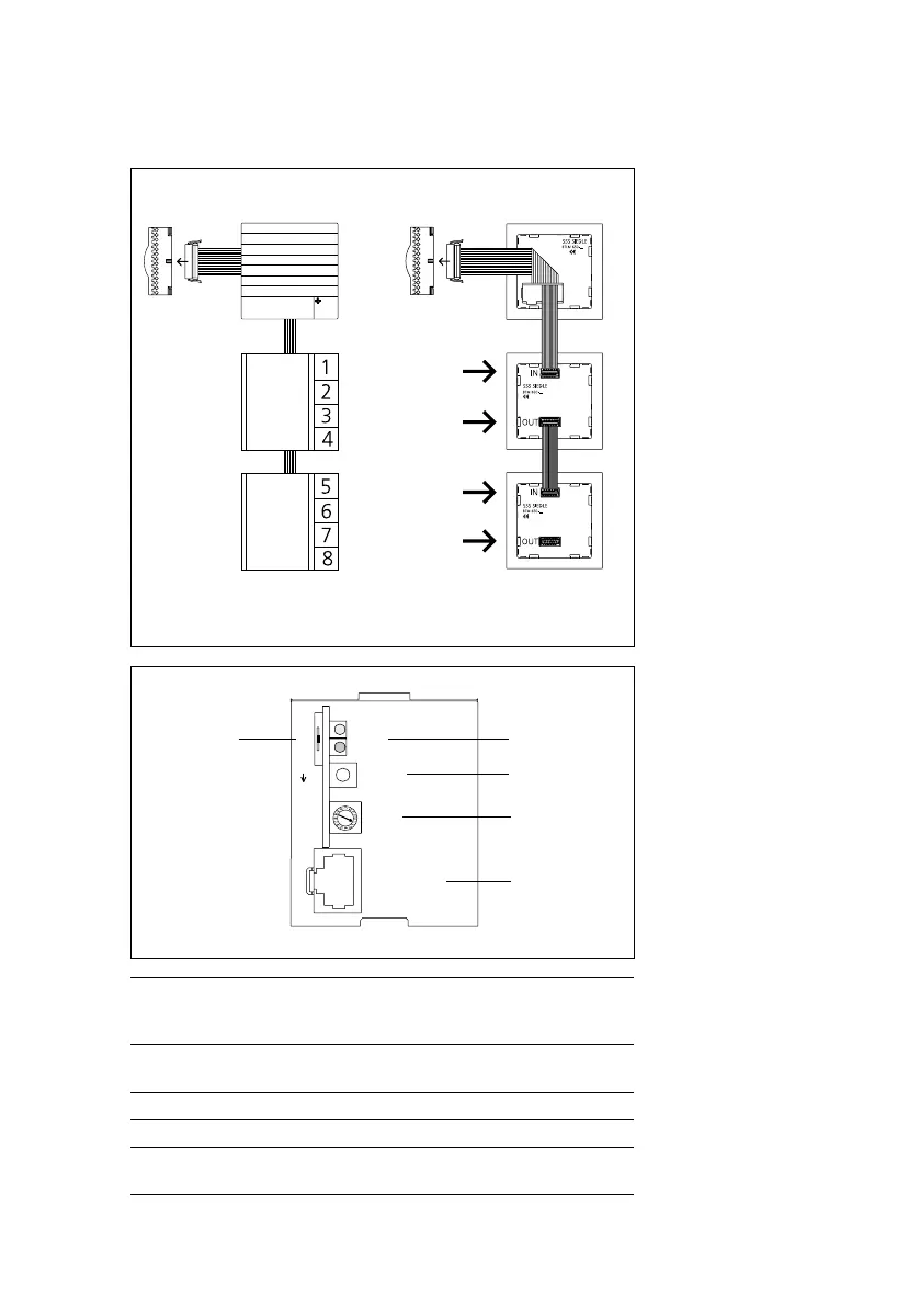
Bus call button module, bus line rectier
Bus call button module
Connection of the bus call button
modules to the bus door loud-
speaker via ribbon cable. The name
plate lighting is supplied from the
terminal block of the BTLM650-04.
If there are more than 20 illuminated
bus call button modules with LED
lighting (BTM650-01, -02, -03,
-04), these must be supplied via an
additional transformer with 12VAC
if a door release is operated within
the system.
Bus line rectier
At bus line rectier BNG650-…, the
operating mode selector switch
must be set to Norm in a new
system (as-delivered status).
If rst series bus telephones are
used within the line, (e.g. B. BTS/
BTC750-0), the operating mode
switch must be set to 1.
For more information, see
page90
Using the “Adr.” rotary switch, the
address is set at the bus line rec-
tier. In single line systems, this is
address1 in the as-delivered status.
This setting does not need to be
altered. In multiple line systems, the
bus line rectiers are addressed in
consecutive sequence.
BTLM 650-04
In-Home-Bus
up to max.
160 call buttons
BTLM 650-04
In-Home-Bus
IN
OUT
IN
OUT
up to max. 40
bus call button module
LED1
LED2
Prog.
Adr.
PRI 602 USB
1-Norm-2 Betriebsart
Mode
b
c
d
e
a
a 1 = Reverse compatible (with BSG650-…)
Standard = Operation as a new system
2 = Function identical to standard
b LED1 = Operational LED
LED2 = Error LED
c Button for programming mode ON/OFF.
d Address setting from 1-15 (1-F) required in multiple-line systems.
e Socket for connection of PRI602-…USB, only available if
ZBVG650-… is plugged in.
Bekijk gratis de handleiding van Jung SI 4 AD, stel vragen en lees de antwoorden op veelvoorkomende problemen, of gebruik onze assistent om sneller informatie in de handleiding te vinden of uitleg te krijgen over specifieke functies.
Productinformatie
| Merk | Jung |
| Model | SI 4 AD |
| Categorie | Niet gecategoriseerd |
| Taal | Nederlands |
| Grootte | 8414 MB |


