JET JWJ-8HH-BLK handleiding
Handleiding
Je bekijkt pagina 10 van 28
10
7.2.2 Installing Jointer to Stand
The jointer is heavy! Use great
care and adequate resources when lifting the
assembly out of the crate and onto the stand! Do
not lift from the ends of the infeed and outfeed
tables. Lift as close to the table seat as possible.
Failure to comply may cause serious injury
and/or damage to the jointer and/or property!
Refer to Figure 7-8:
1. Place the main jointer (A) onto the stand (B).
Align the main jointer threaded mounting holes
with the mounting holes on the stand top.
2. Using three M10 x 20 screws, 10mm lock
washers, and 10mm flat washers (C), go
through the bottom of the stand top and attach
the main jointer to the stand.
Figure 7-8
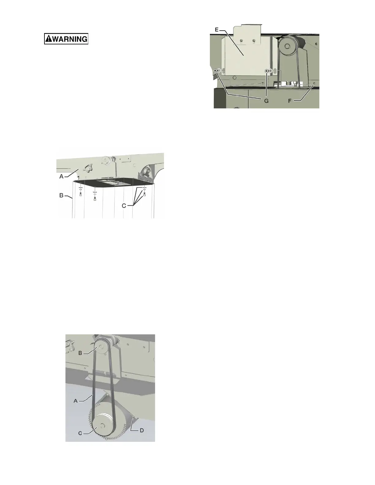
7.2.3 Installing Drive Belts
Refer to Figures 7-9 & 7-10 :
1. There are two drive belts (A). Install both belts
over the cutterhead pulleys (B) and motor
pulleys (C). You should be able to walk the belts
onto the pulleys. If not, loosen the four motor
mounting bolts (D) and slide the motor up to
install belts. After belts are installed, move the
motor down to properly tension the drive belts,
then firmly tighten the motor mounting bolts.
2. Install the belt cover (E) to the jointer table
assembly (F) using two M8x10 mounting
screws and 8mm flat washers (G).
Figure 7-9
Figure 7-10
7.2.4 Installing Fence Base Assembly
and Fence
Fence Base Assembly
Refer to Figures 7-11A, 7-11B, & 7-11C:
1. Assemble two M10x35 mounting screws with
10mm lock washers and 10mm flat washers
(A).
2. Insert mounting screws into threaded mounting
holes (D & E) on the jointer table assembly.
Turn mounting screws several times to hold
them in place.
3. Align fence base assembly mounting slots (B &
C) above mounting screws and slide down over
screws. Make sure the flat washers/lock
washers remain on the outside of the fence
base assembly mounting plate.
4. Further tighten the mounting screws to be close
to the fence base assembly mounting plate, but
still loose.
5. Position the fence base assembly so that the
top surface of the lower bed (F) is level with the
outfeed table surface (G). Firmly tighten the
mounting screws (A).
6. Reach beneath the lower bed (F) and hold the
T-nut (J). Loosen and remove the shipping hex
bolt (I) from the upper bed (H). Be careful not to
drop and lose the T-nut.
7. Replace shipping hex bolt with locking
handle/bolt (K, included in accessory bag).
Thread the locking handle/bolt into the T-nut (J)
beneath the lower bed (F).
8. Check the fence base assembly upper bed (H)
clearance by loosening the upper bed
adjustment lock handle (K) and slide the upper
bed towards the jointer tables. The fence base
assembly upper bed should clear the jointer
outfeed table surface (G).
IMPORTANT: If the top surface of the fence base
assembly lower bed (F) is not level with the outfeed
table surface (G), damage to the outfeed table’s JET
Black coating could occur.
Bekijk gratis de handleiding van JET JWJ-8HH-BLK, stel vragen en lees de antwoorden op veelvoorkomende problemen, of gebruik onze assistent om sneller informatie in de handleiding te vinden of uitleg te krijgen over specifieke functies.
Productinformatie
| Merk | JET |
| Model | JWJ-8HH-BLK |
| Categorie | Niet gecategoriseerd |
| Taal | Nederlands |
| Grootte | 9382 MB |


