Intergas Xtend Split handleiding
Handleiding
Je bekijkt pagina 27 van 88
27
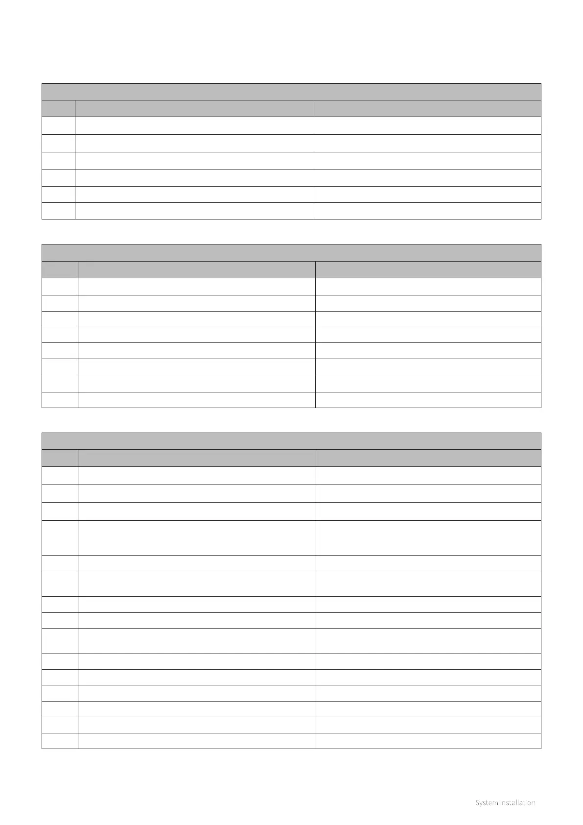
Fittings - Instrumentation
Tag Description Signal
T01 NTC (clip-on 1/2") T (ºC) Refrigerant line (gas)
T02 NTC (clip-on 1/4") T (ºC) Refrigerant line (liquid)
T03 NTC (clip-on 22mm) T (ºC) Indoor unit flow
T04 NTC (clip-on 22mm) T (ºC) Indoor unit return
T05 NTC (clip-on 22mm S1 flow integral to boiler) T (ºC) Boiler heating flow to low loss header
T42 Outdoor sensor and housing (optional)
T (ºC) outdoor
T43 Remote flow temperature sensor (optional) T (ºC) Heating system flow
P01 System pressure sensor (integral to boiler)
Fittings - Process
Tag Description Notes
LLH01 Open distributor (Low loss header)
V01 Venting Manual air vent top le of the indoor unit
V02 System filter (required) Positioned in the CH system return line to the indoor unit
V03 Non return valve (required)
Positioned in the boiler return line (L03) from the low loss
header to the boiler. Ensure no non-return valve has already
been installed (i.e. to prevent thermo-syphoning).
V04 Venting Manual venting top le of the boiler
V05 Pressure relief valve
Built into the boiler, the discharge pipework must be routed and
terminated as stated within the installation manual or BS 6798
V06 Filling valve connection For filling the system / CH water
V07 Full-flow ball type isolation valve (optional) To assist when cleaning or flushing the system filter
V08
Gas line isolation valve 1/2" flared joint union
(service connection point)
Service point for refrigerant actions
V09 Liquid line isolation valve 1/4" flared joint union
Pm01 Indoor unit CH pump ErP modulating Primary pump for the CH system installation
Pm02 Boiler CH pump ErP modulating Secundary pump for the CH system installation
Pm03 External pump for a buer vessel (optional)
HE01 Indoor unit plate heat exchanger
HE02 Boiler heat exchanger
Lines
Tag Description Notes (minimum diameters)
L01 Cold system water return line from the CH circuit to the indoor unit Ø22 mm (compression)
L02 Hot system water flow line from the indoor unit to the CH circuit Ø22 mm (compression)
L03 Low loss header return line to the boiler Ø22 mm (compression)
L04 Boiler flow line to the low loss header Ø22 mm (compression)
L05 Refrigerant line (gas) 1/2 inch, flared joint union (must be insulated)
L06 Refrigerant line (liquid) 1/4 inch, flared joint union (must be insulated)
Bekijk gratis de handleiding van Intergas Xtend Split, stel vragen en lees de antwoorden op veelvoorkomende problemen, of gebruik onze assistent om sneller informatie in de handleiding te vinden of uitleg te krijgen over specifieke functies.
Productinformatie
| Merk | Intergas |
| Model | Xtend Split |
| Categorie | Niet gecategoriseerd |
| Taal | Nederlands |
| Grootte | 11570 MB |


