Intergas Xclusive 24 handleiding
Handleiding
Je bekijkt pagina 70 van 92
70
Before the minimum output correction is performed, the
maximum output and minimum output measurements must
be completed. The measured CO
2
(H) value at maximum output
is important for determining the correct value for the setting at
minimum output (see §9.10.1 and §9.10.2).
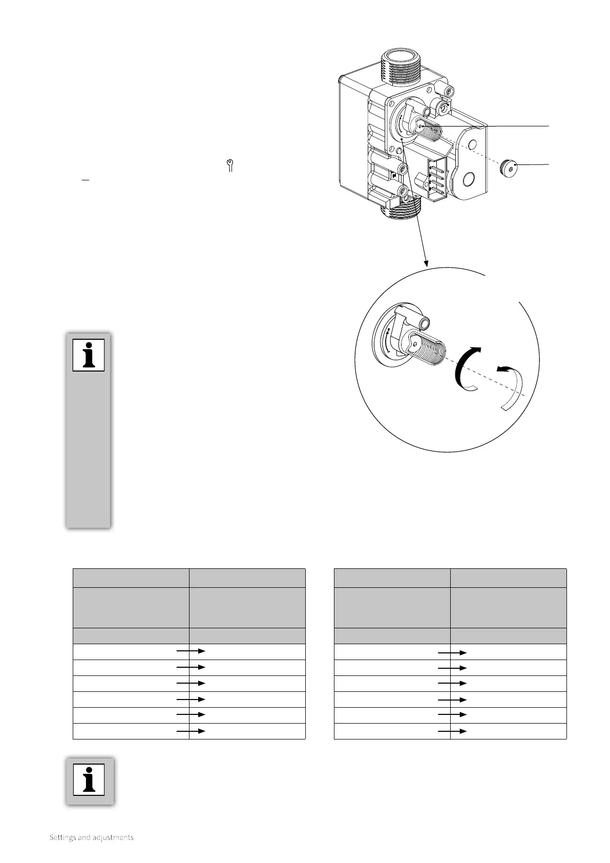
A. Remove the dust cap of the gas valve so that the adjustment
screw is accessible.
B. Switch on the boiler at minimum output. To do this, tap
simultaneously the Service button and the Minus button
until the capital letter LL appears on the right display.
C. Wait until the readout of the flue gas analyser is stable (at
least 3 minutes).
D. Measure the CO
2
(L) value.
E. Using the adjustment screw B, set the correct CO
2
(L) value.
For the correct CO
2
(L) setting value, see Tables 4a or 4b.
F. Reattach the cover screw of the gas valve so that the
adjustment screw is sealed.
G. Check the measurements at both maximum output and
minimum output noted in §9.10.1 and §9.10.2 (start with
Step F in §9.10.1) to ensure the correct flue gas emission
levels are obtained.
9.10.3 Minimum output correction
Adjustment screw
Dust cap
► Select the correct table depending on the
applicable gas category:
4a: natural gas (G20)
4b: LPG 3P (G31)
► The maximum output measurement
value is important for a correct
adjustment. This measurement value
was noted during the maximum output
measurement CO
2
(H) (see §9.10.1, Step
H).
► Turning the adjustment screw to the right
increases CO
2
.
Turning to the le decreases CO
2
.
► Turn the adjustment screw with small
steps and wait aer each turn until the
measurement stabilises.
Use a T15 Torx drive for the dust cap
removal & oset adjustments
Clockwise to
increase CO
2
Anticlockwise to
decrease CO
2
Table 4a: Checking CO
2
(L) levels for Natural gas
(open casing)
Table 4b: Checking CO
2
(L) levels for LPG (open
casing)
LPG G31 (37 mbar)
Measured value at
maximum output
(see §9.10.1, Step H)
Setting value minimum
output
(= CO
2
(H) - 0.3)
CO
2
(H) [%] CO
2
(L) [%]
10.8 10.5 ± 0.1
10.6 10.3 ± 0.1
10.4 10.1 ± 0.1
10.2 9.9 ± 0.1
10.0 9.7 ± 0.1
9.8 9.5 ± 0.1
Example (when using natural gas G20)
► During maximum output, a CO
2
(H) level of
9.0% is measured. In this instance a minimum
output CO
2
value must be 8.7 ± 0.1%.
Natural Gas G20 (20 mbar)
Measured value at
maximum output
(see §9.10.1, Step H)
Setting value minimum
output
(= 0.5 x CO
2
(H) + 4.2)
CO
2
(H) [%] CO
2
(L) [%]
9.6 9.0 ± 0.1
9.4 8.9 ± 0.1
9.2 8.8 ± 0.1
9.0 8.7 ± 0.1
8.8 8.6 ± 0.1
8.6 8.5 ± 0.1
Bekijk gratis de handleiding van Intergas Xclusive 24, stel vragen en lees de antwoorden op veelvoorkomende problemen, of gebruik onze assistent om sneller informatie in de handleiding te vinden of uitleg te krijgen over specifieke functies.
Productinformatie
| Merk | Intergas |
| Model | Xclusive 24 |
| Categorie | Niet gecategoriseerd |
| Taal | Nederlands |
| Grootte | 12726 MB |


