IFM PG1715 handleiding
Handleiding
Je bekijkt pagina 21 van 61
Electronic manometer PG17xx
© ifm electronic gmbh 11601190 / 01 07 / 2025 21
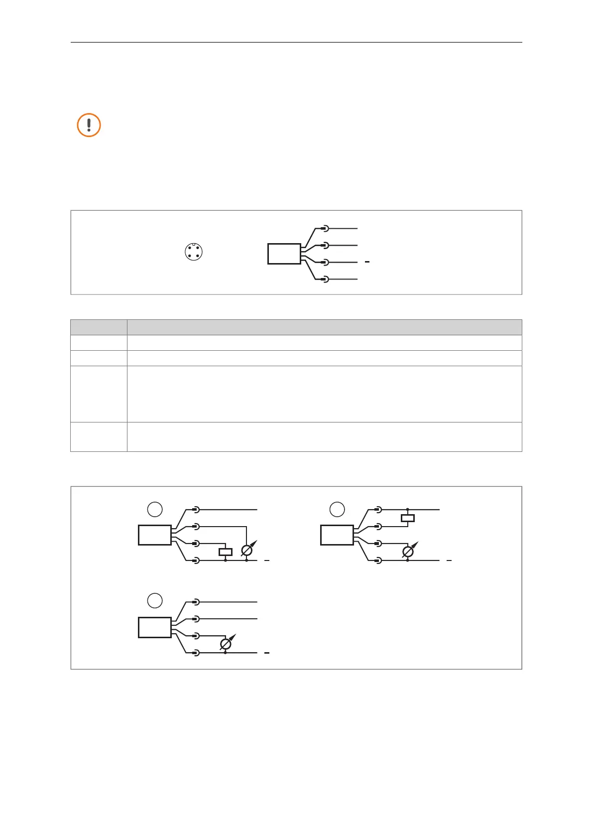
7 Electrical connection
The unit must be connected by a qualified electrician.
Observe the national and international regulations for the installation of electrical equipment.
Voltage supply according to SELV, PELV.
Disconnect power.
Connect the unit as follows:
43
2 1
L
1
2
3
4
OUT2
L+
MP1
Fig.8: Wiring diagram
Pin Assignment
1 L+
3 L-
4 (MP1)
MP =
Multifunc-
tional
• Switching signal pressure
• IO-Link
• OFF (output switched to high impedance)
• Deactivated (switching channel permanently high or low depending on the switch-point logic)
2 (OUT2) • Analogue signal pressure
• OFF (output switched to high impedance)
Circuit examples:
L
1
2
4
3
L+
L
1
4
2
3
L+
1 2
L
1
4
2
3
L+
IO-Link
3
1: 1x positive switching (PnP) / 1x analogue 2: 1x negative switching (nPn) / 1x analogue
3: IO-Link / 1x analogue
Bekijk gratis de handleiding van IFM PG1715, stel vragen en lees de antwoorden op veelvoorkomende problemen, of gebruik onze assistent om sneller informatie in de handleiding te vinden of uitleg te krijgen over specifieke functies.
Productinformatie
| Merk | IFM |
| Model | PG1715 |
| Categorie | Niet gecategoriseerd |
| Taal | Nederlands |
| Grootte | 5338 MB |


