IFM PG1706 handleiding
Handleiding
Je bekijkt pagina 13 van 55
Electronic manometer PG17xx
13
Information about available accessories at www.ifm.com
5.2.4 G 1 flange / G1 adapter
The sensor is sealed with the sealing ring at the back of the process connection.
u Ensure that the sealing area on the flange/ adapter is flush with the tapped hole.
u Ensure that the sealing area has a surface structure of at least Rz = 6.3 (observe DIN EN ISO
1179-1).
5.3 Use in hygiene areas to 3-A and EHEDG
The sensor is suited for CIP (cleaning in process) and SIP (sterilisation in place) when installed
correctly.
u Observe the application limits (temperature and material resistance) according to the data
sheet.
The gasket of the system interface must not be in contact with the sealing point of the sensor.
u Use self-draining installation.
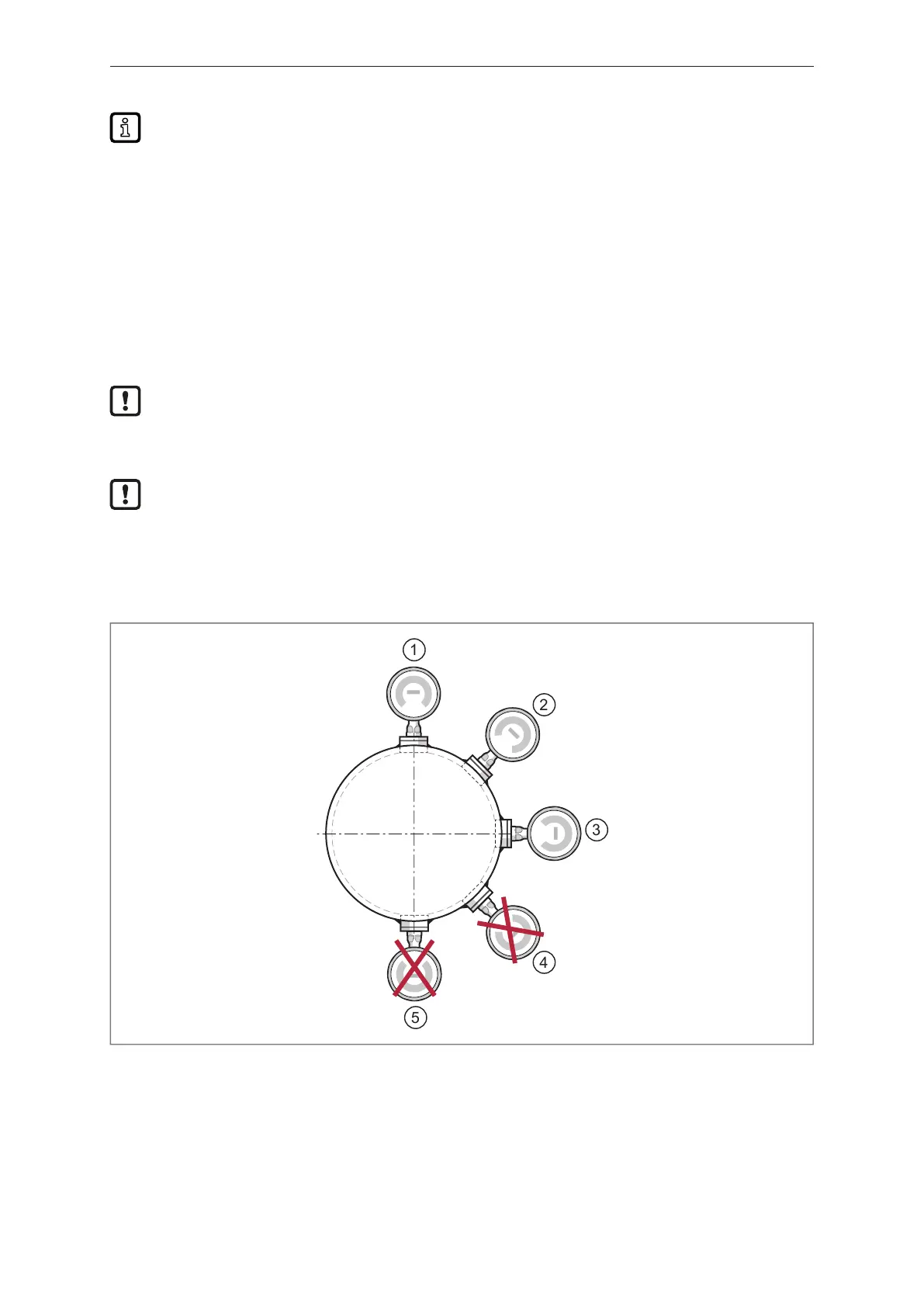
u Leakage ports must be clearly visible and must be installed facing downwards for vertical pipes.
u The positioning of the sensor must be observed to ensure the mounting adapter will self-drain: Do
not install the unit in positions 4 and 5.
1
2
3
4
5
Fig.3: Mounting position for use in hygienic areas in accordance with 3-A and EHEDG
Avoid dead space:
Make sure there is no dead space in the system where product residues, microorganisms or cleaning
agents can accumulate. The contacting parts of the sensing face must be easy to reach for cleaning
and must not be in a dead space.
u For any structures in a tank, direct water jet cleaning must be possible. Cleaning of dead spaces
must be possible.
Bekijk gratis de handleiding van IFM PG1706, stel vragen en lees de antwoorden op veelvoorkomende problemen, of gebruik onze assistent om sneller informatie in de handleiding te vinden of uitleg te krijgen over specifieke functies.
Productinformatie
| Merk | IFM |
| Model | PG1706 |
| Categorie | Niet gecategoriseerd |
| Taal | Nederlands |
| Grootte | 4616 MB |


