IFM PG1705 handleiding
Handleiding
Je bekijkt pagina 34 van 55
PG17xx Electronic manometer
34
Window mode:
u Select [ModE] and set the switch-point mode: [WInd].
u Select [HYSt] and set the hysteresis.
u Approach the system pressure for the upper limit of the window section and keep it constant.
u Select [tSP1] and set [Yes].
w The current value is adopted as switch point SP1.
u Approach the system pressure for the lower limit of the window section and keep it constant.
u Select [tSP2] and set [Yes].
w The current value is adopted as switch point SP2.
If an invalid measured value outside the measuring range is using for teaching, [UL] or [OL] and
[FAIL] are displayed alternately. The value is not adopted.
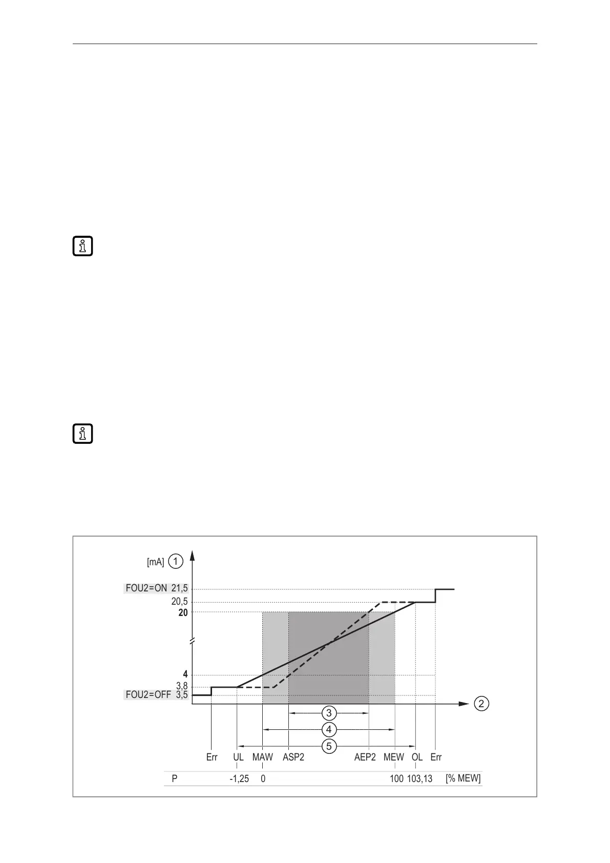
10.3.2 Analogue signal
The device provides an analogue signal proportional to the process value.
Within the measuring range the analogue signal is between 4...20 mA.
The analogue signal is invertible:
• 4...20mA for setting [ou2] = I
• 20...4mA for setting [ou2] = InEG
The measuring range is scalable: The measuring range can be limited using the [ASP2] and [AEP2]
parameters.
Minimum distance between [ASP2] and [AEP2] = 20 % of the final value of the measuring
range.
If measured values are outside the display range or in case of an error, messages are displayed (UL,
OL, Err) and the analogue signal goes to a lower or upper limit value (Ò figure).
The [FOU] parameter can be used to set the behaviour of the analogue output in the event of an error
Ò chapter Error behaviour of the outputs.
Analogue signal with setting [ou2] = [I]:
MEWMAW AEP2
ASP2
[% MEW]
P -1,25 0 100 103,13
4
3,8
20
20,5
21,5FOU2
= ON
FOU2
= OFF
[mA]
ULErr ErrOL
3,5
1
2
3
4
5
Bekijk gratis de handleiding van IFM PG1705, stel vragen en lees de antwoorden op veelvoorkomende problemen, of gebruik onze assistent om sneller informatie in de handleiding te vinden of uitleg te krijgen over specifieke functies.
Productinformatie
| Merk | IFM |
| Model | PG1705 |
| Categorie | Niet gecategoriseerd |
| Taal | Nederlands |
| Grootte | 4616 MB |


