IFM PG1705 handleiding
Handleiding
Je bekijkt pagina 32 van 55
PG17xx Electronic manometer
32
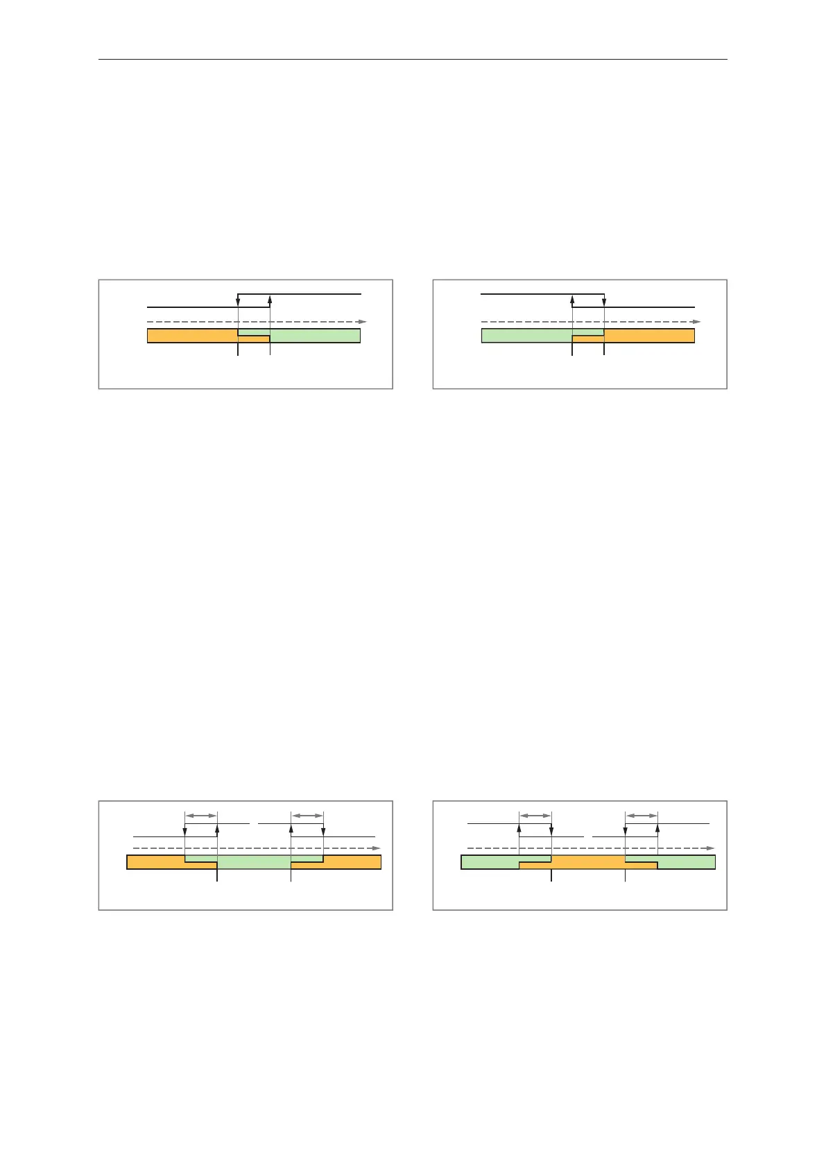
When setting the parameters via IO-Link, the position of the switch points can be freely selected: SP1
can be below or above SP2. The lower switch point is the reset point. In the example shown, SP1 is
the switch point and SP2 is the reset point.
When setting the parameters via the device keys, SP1 must be greater than SP2. If the order of the
switch points is subsequently reversed via IO-Link, then SP1 must be smaller than SP2 in the future
when setting parameters via the device keys.
When teaching, the switch point is set directly to the taught process value. The following applies:
[TeachSP1] sets SP1, [TeachSP2] sets SP2.
The hysteresis will be ignored in Two Point Mode.
SP1
low
high
SP2
(TP1)(TP2)
PDV
0
1
Fig.15: [Two Point Mode] / [High active]
SP1: Switch point 1
SP2: Switch point 2
TP1: Teach point 1 (= SP1)
TP2: Teach point 2 (= SP2)
SP1
high
low
SP2
(TP1)(TP2)
PDV
1
0
Fig.16: [Two Point Mode] / [Low active]
SP1: Switch point 1
SP2: Switch point 2
TP1: Teach point 1 (= SP1)
TP2: Teach point 2 (= SP2)
Window mode
Two switch points (SP1) and (SP2) are manually set or taught.
The two switch points define a window area.
When setting the parameters via IO-Link, the position of the switch points can be freely selected: SP1
can be below or above SP2. The lower switch point is the lower limit value, the higher switch point is
the upper limit value of the window area.
When setting the parameters via the device keys, SP1 must be greater than SP2. If the order of the
switch points is subsequently reversed via IO-Link, then SP1 must be smaller than SP2 in the future
when setting parameters via the device keys.
When teaching, the switch point is set directly to the taught process value. The following applies:
[TeachSP1] sets SP1, [TeachSP2] sets SP2.
When the process data value enters the window area, the status of the switching signal channel
changes immediately when the switch points are exceeded/not reached.
If the process data value leaves the window area, the status of the switching signal channel changes
when the switch point plus hysteresis (SP1+H or SP2-H) is exceeded/not reached.
SP2 SP1
(TP2) (TP1)
lowlow
high
PDV
0 0
1
H
H
Fig.17: [Window Mode] / [High active]
H: Hysteresis
SP1: Switch point 1
SP2: Switch point 2
TP1: Teach point 1 (= SP1)
TP2: Teach point 2 (= SP2)
SP2 SP1
(TP2) (TP1)
low
highhigh
PDV
0
1 1
H
H
Fig.18: [Window Mode] / [Low active]
H: Hysteresis
SP1: Switch point 1
SP2: Switch point 2
TP1: Teach point 1 (= SP1)
TP2: Teach point 2 (= SP2)
Bekijk gratis de handleiding van IFM PG1705, stel vragen en lees de antwoorden op veelvoorkomende problemen, of gebruik onze assistent om sneller informatie in de handleiding te vinden of uitleg te krijgen over specifieke functies.
Productinformatie
| Merk | IFM |
| Model | PG1705 |
| Categorie | Niet gecategoriseerd |
| Taal | Nederlands |
| Grootte | 4616 MB |


