IFM AL2507 handleiding
Handleiding
Je bekijkt pagina 17 van 27
IO-Link input/output module AL2507
17
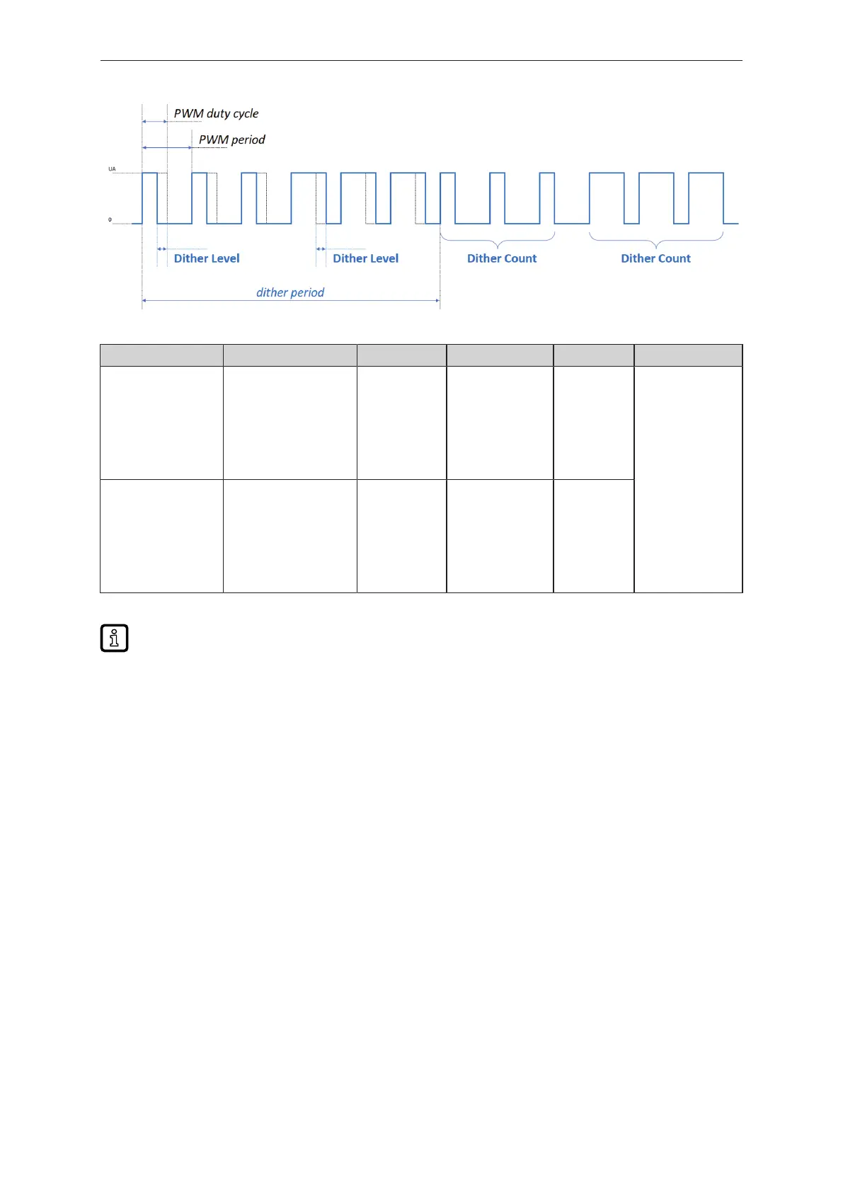
Fig.3: Dithering_example
Parameter Index Subindex Value Increments Factory setting
Level 15020 for X1.0
15021 for X1.1
15022 for X1.2
15023 for X1.3
15024 for X1.4
15025 for X1.5
15026 for X1.6
15027 for X1.7
1 0 – 250 (‰) 0.1 0
Count 15020 for X1.0
15021 for X1.1
15022 for X1.2
15023 for X1.3
15024 for X1.4
15025 for X1.5
15026 for X1.6
15027 for X1.7
2 0 - 20 1
Tab.5: Parameter PWM dither X1.x
[Level] = 0 deactivates dithering and/or
[Count] = 0 deactivates dithering.
4.12 PWM-I output
This function is only available in operating mode [Acyclic Enhanced].
Pin 4 of ports X1.0 and X1.1 is the PWM-I output. The PWM-I output is activated as follows:
• Port mode = 07 in IO-Link parameter 15105
• PDOut [X1.x] (PWM-I requested current) > 0 in PDOut PLC-Out Word 6/8
• DO [X1.x-1] (pin 4) = 1 in PDOut PLC-Out Word 2 (1 activates the PWM-I output)
• PID [X1.x] according to the connected load: Configuration example (Ò/18)
4.12.1 Configuration
The following settings can be made for the PWM-I output:
• Current (setting via process data)
The output current can be set separately for both ports. The value is written via [Process data out]
(Ò IODD).
• Frequency (setting via IO-Link parameters)
A common frequency value can be configured for both ports:
Bekijk gratis de handleiding van IFM AL2507, stel vragen en lees de antwoorden op veelvoorkomende problemen, of gebruik onze assistent om sneller informatie in de handleiding te vinden of uitleg te krijgen over specifieke functies.
Productinformatie
| Merk | IFM |
| Model | AL2507 |
| Categorie | Niet gecategoriseerd |
| Taal | Nederlands |
| Grootte | 2204 MB |


