IFM AL2507 handleiding
Handleiding
Je bekijkt pagina 10 van 27
AL2507 IO-Link input/output module
10
4.7 Digital input filters
The input signals can be changed via different filters before they are passed on via IO-Link. The
following filters are available and are applied to the input signal in this order:
1. Debounce
2. Hold
3. Inverting
Digital input
Input
debounce
Input hold Input invert
IO-Link
process data
Each of these filters can be configured separately via IO-Link. More information is available in the
IODD at documentation.ifm.com.
The device detects signals of a length of min. 2 ms. Shorter signals are not detected.
Periodic signals are only detected reliably if the signal period is at least twice as long as the
cycle time.
The precision of the digital input filters is ± 1 ms.
4.7.1 Debouncing
The input debouncing filter suppresses noise signals caused by mechanical switches, contacts or
relays. The filter provides the input signals at the filter output with a delay (debounce time). All signals
shorter than the set debounce time are ignored by the filter.
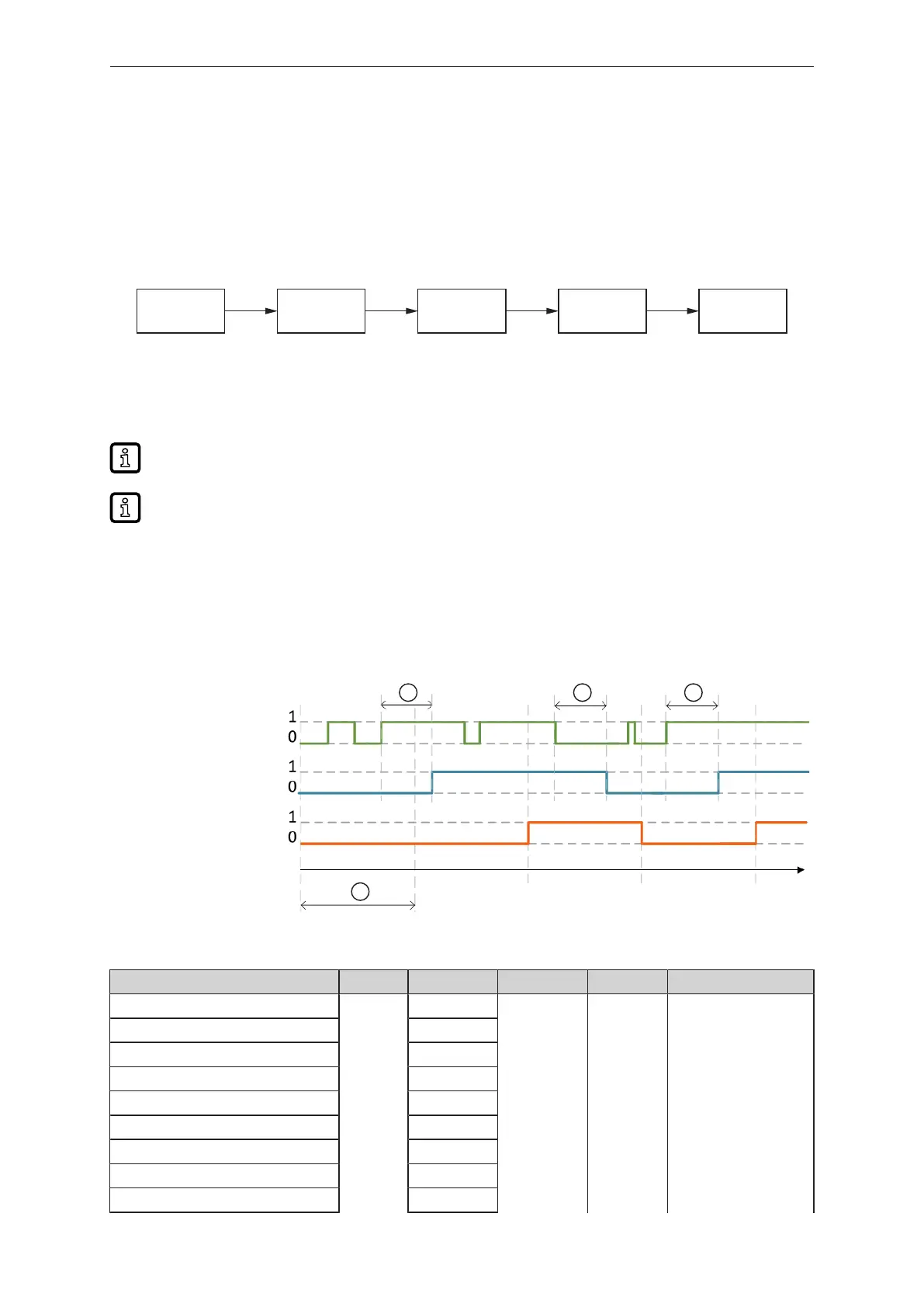
Time diagram debounce filter:
t
1 1 1
2
digital input
Debounce filter output
IO-Link
process data
1: Debounce time
2: Cycle time
Parameter Index Subindex Value (ms) Increments Factory setting
Input Debounce time X1.0 - 1 15100 1 0 – 50 1 0
Input Debounce time X1.0 - 2 2
Input Debounce time X1.1 - 1 3
Input Debounce time X1.1 - 2 4
Input Debounce time X1.2 - 1 5
Input Debounce time X1.2 – 2 6
Input Debounce time X1.3 - 1 7
Input Debounce time X1.3 - 2 8
Input Debounce time X1.4 – 1 9
Bekijk gratis de handleiding van IFM AL2507, stel vragen en lees de antwoorden op veelvoorkomende problemen, of gebruik onze assistent om sneller informatie in de handleiding te vinden of uitleg te krijgen over specifieke functies.
Productinformatie
| Merk | IFM |
| Model | AL2507 |
| Categorie | Niet gecategoriseerd |
| Taal | Nederlands |
| Grootte | 2204 MB |


