Icom IC-FR5300 handleiding
Handleiding
Je bekijkt pagina 13 van 21
1
2
3
4
5
6
7
8
9
10
11
12
13
14
15
16
17
18
19
20
21
6
2
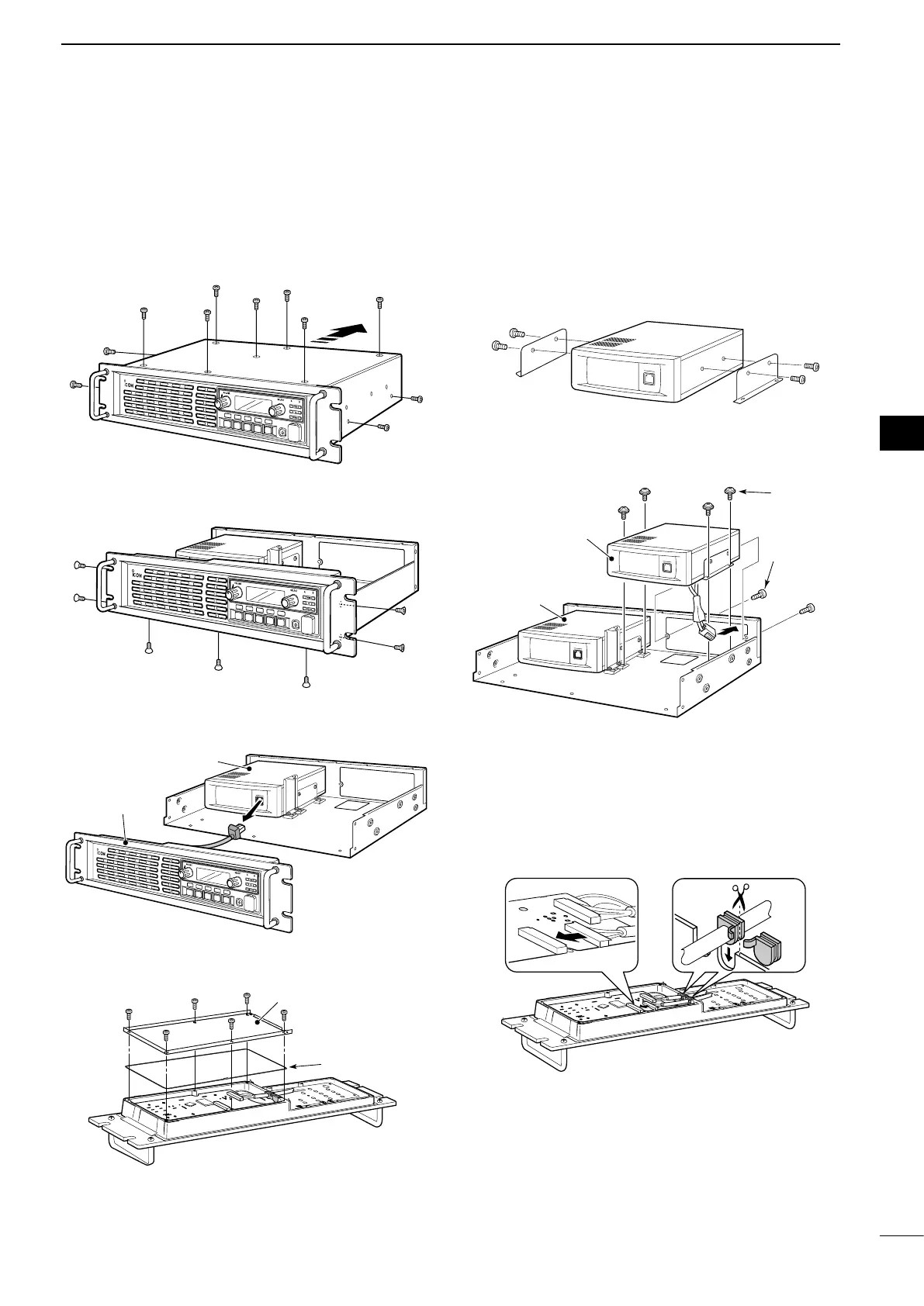
INSTALLATION AND CONNECTIONS
D
Installation
• Install the UR-FR5300 or UR-FR6300
(channel extension module)
1. Attach the supplied single brackets to both sides
of the channel extension module, and tighten the
2 supplied screws (M4 × 8 mm) on each side.
2. Install the channel extension module using the
supplied screws (Tapping screws: M3 × 8 mm,
Set screws: M3 × 6 mm), as shown below.
• Connect the control cable
1. Connect the supplied control cable to J502 on the
front board, as shown below.
2. Cut the rubber caps of the control cables,
then insert the rubber caps to the front panel’s
chassis, as shown below.
J502
Set screws
Tapping
screws
Channel module
(original)
Channel extension
module
D
Opening Case
1.
Remove the 7 screws from the top and the 2
screws each from both sides of the repeater, then
slide off the top cover in the direction of the arrow,
as illustrated below.
2. Remove the 3 screws from the bottom and the 2
screws each from both sides of the repeater.
3. Disconnect the control cable from the channel
module (original), then remove the front panel.
4. Remove the 6 screws from the front panel, then
remove the shielding plate and rubber seal.
P
0
P
1
P
2
P
3
P
4
P
0
P
1
P
2
P
3
P
4
P
0
P
1
P
2
P
3
P
4
Channel module
(original)
Front panel
Rubber seal
Shielding plate
■
Installing the Channel extension module
Bekijk gratis de handleiding van Icom IC-FR5300, stel vragen en lees de antwoorden op veelvoorkomende problemen, of gebruik onze assistent om sneller informatie in de handleiding te vinden of uitleg te krijgen over specifieke functies.
Productinformatie
| Merk | Icom |
| Model | IC-FR5300 |
| Categorie | Niet gecategoriseerd |
| Taal | Nederlands |
| Grootte | 2740 MB |
Caratteristiche Prodotto
| Ingebouwd display | Ja |
| Vermogensverbruik (max) | 50 W |
| Ondersteunde beveiligingsalgoritmen | SNMP |
| Rack-montage | Ja |
| Aantal kanalen | 32 kanalen |


