Icom IC-FR5300 handleiding
Handleiding
Je bekijkt pagina 11 van 21
1
2
3
4
5
6
7
8
9
10
11
12
13
14
15
16
17
18
19
20
21
2
4
INSTALLATION AND CONNECTIONS
■
Unpacking
After unpacking, immediately report any damage to
the delivering carrier or dealer. Keep the shipping
cartons.
For a description and a diagram of accessory
equipment included with the repeater, see ‘SUPPLIED
ACCESSORIES’ on page vi of this manual.
■
Selecting a location
Select a location for the repeater that allows adequate
air circulation, free from extreme heat, cold, or vibra-
tions, and other electromagnetic sources.
Never place the transceiver in areas such as:
• Temperatures below –25°C (–13°F) or above +55°C
(+131°F): European or Australian versions, below
–30°C (–22°F) or above +60°C (+140°F): other ver-
sions.
• An unstable place that slopes or vibrates.
• In direct sunlight.
• High humidity and temperature environments.
• Dusty environments.
• Noisy environments.
■
Antenna connection
For radio communications, the antenna is a critical
component, along with output power and sensitivity.
Select antenna(s), such as a well-matched 50 ø an-
tenna and feedline. We recommends 1.5:1 or better
of Voltage Standing Wave Ratio (VSWR) for the de-
sired band. Of course, the transmission line should be
a coaxial cable.
CAUTION: DO NOT install the repeater without a
lightning arrestor to help protect the repeater from
lightning.
NOTE:
Many publications describe proper
antennas and their installation. Check with your
local dealer for more information and
recommendations.
■ Power supply connection
Conrm the repeater is OFF before connecting the
DC power cable.
R WARNING! NEVER apply more than 16 V DC
to the DC power receptacle on the repeater rear
panel. This could cause a re or damage the re-
peater.
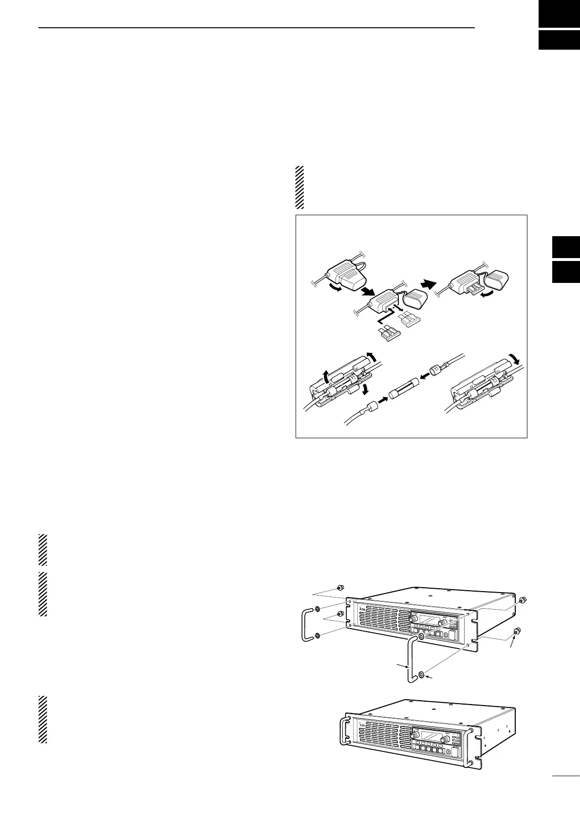
■ Mounting the repeater
D Using the supplied handles
When mounting the repeater into a 19-inch rack, use
the supplied handles. Install the handles on the re-
peater’s front panel, as described below.
1. Attach the supplied handles to both sides of the
repeater’s front panel with the spacers, and then
tighten the screws.
P
0
P
1
P
2
P
3
P
4
Handle
Spacer
Screw
2. The completed installation should look like this.
P
0
P
1
P
2
P
3
P
4
■
Replacing fuse
If a fuse blows, or the repeater stops functioning, nd
the source of the problem, repair it, and then replace
the damaged fuse with a new rated one.
CAUTION: DO NOT replace the fuse with the DC
power cable connected to the power source.
Disconnect the cable to prevent electric shock and/
or equipment damage.
D
Line fuse replacement
Fuse rating: 32 V 20 A
USE only a specified fuse.
Fuse rating: 125 V 1 A
Bekijk gratis de handleiding van Icom IC-FR5300, stel vragen en lees de antwoorden op veelvoorkomende problemen, of gebruik onze assistent om sneller informatie in de handleiding te vinden of uitleg te krijgen over specifieke functies.
Productinformatie
| Merk | Icom |
| Model | IC-FR5300 |
| Categorie | Niet gecategoriseerd |
| Taal | Nederlands |
| Grootte | 2740 MB |
Caratteristiche Prodotto
| Ingebouwd display | Ja |
| Vermogensverbruik (max) | 50 W |
| Ondersteunde beveiligingsalgoritmen | SNMP |
| Rack-montage | Ja |
| Aantal kanalen | 32 kanalen |


