Handleiding
Je bekijkt pagina 15 van 77
13
Vacuum pumping
-Do use Nitrogen.
Air tight procedure
Completion
of Ref.
Piping
Repairing
of Leakage
Part
Check of
Pressure
Decrease
Applying
Nitrogen
Gas
Pass
Procedure
Connect the gauge manifold using charging hoses with a nitrogen
cylinder to check joints of the liquid line and the gas line stop
valves.
Perform the air tight test.
Don't open the gas line stop valves.
Apply nitrogen gas pressure of 4.15MPa.
Check any gas leakage at the flare nut connections, or brazed
parts by gas leak detector or foaming agent.
Gas pressure doesn’t decrease, which is OK.
After the air tight test, release nitrogen gas.
An excess or a shortage of refrigerant is the main cause of trouble to the unit. Charge the correct quantity of refrigerant
according to the description in the manual.
Check refrigerant leakage in detail. If a large refrigerant leakage occurs, it will cause difficulty in breathing, harmful
gases or fire will occur if a fire is being used in the room.
Charge hose
(for R32)
Piping insulation procedure
Insulation
( )field-supplied
(6) After finishing connecting the refrigerant pipes, keep it warm with
the insulation material as shown in the right figure.
For outdoor unit side, surely insulate every piping including valves.
Cover piping joints with pipe cover.
Using piping tape, apply taping starting from the entry of
outdoor unit. Fix the end of piping tape with adhesive tape.
When piping has to be arranged through above ceiling, closet or area
where temperature and humidity are high, wind additional commercially
sold insulation for prevention of condensation.
5. Air tight test
Clamp(field-supplied)
Insulation (field-supplied)
Refrigerant pipe
(field-supplied)
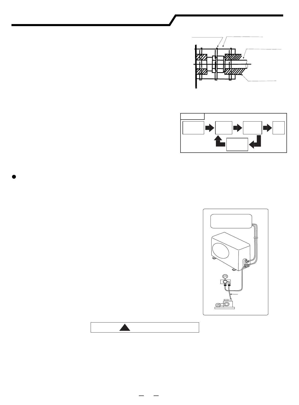
(1) Remove the service port cap of the stop valve on the gas pipe
side of the outdoor unit.
(2) Connect the manifold gauge and vacuum pump to the service port
of the stop valve on the gas pipe side of the outdoor unit.
(3) Run the vacuum pump. (Work for more than 15 minutes.)
(4) Check the vacuum with the gauge manifold valve, then close the
gauge manifold valve and stop the vacuum pump.
(5) Leave it as is for one or two minutes. Make sure that the pointer
of the manifold gauge remains in the same position. Confirm that
the pressure gauge shows -0.101MPa (or -760mmHg).
(6) Remove the manifold gauge quickly from the service port of the
stop valve.
(7) After refrigerant pipes are connected and evacuated, fully open
all stop valves on both sides of gas pipe and liquid pipe.
(8) Open adjusted valve to add refrigerant.
(9) Tighten the cap to the service port .
(10) Retighten the cap.
(11) Leak test foam with halogen leak detector to check the flare nut
and brazing Carolina Department leaks. Use foam that does not
generate ammonia (NH3) in the reaction.
Indoor unit
Outdoor unit
Manifold
valve
Pressure
gauge
Vacuum
pump
Fig.9.2
Installation instructions
6. Vacuum pumping and charge refrigerant
!
CAUTION
Bekijk gratis de handleiding van Hisense AUW175U6RP4, stel vragen en lees de antwoorden op veelvoorkomende problemen, of gebruik onze assistent om sneller informatie in de handleiding te vinden of uitleg te krijgen over specifieke functies.
Productinformatie
| Merk | Hisense |
| Model | AUW175U6RP4 |
| Categorie | Airco |
| Taal | Nederlands |
| Grootte | 9007 MB |


