Hayward Plug N Clear handleiding
Handleiding
Je bekijkt pagina 35 van 200
EN
English
Plug n Clear™ Salt Chlorinator 5
Contents
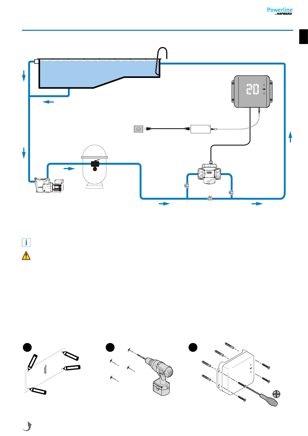
3. INSTALLING THE DEVICE
3.1. INSTALLATION DIAGRAM
Power LED
Controlbox
Power brick
Pump
Filter
maximum
2 metres
Electrolysis
cell
(flow switch included)
110-230VAC
protected plug
3.2. INSTALLING THE PLUG N CLEAR™ CONTROL BOX ON THE WALL
Mount the unit on the wall.
The unit must be installed in the plant room (dry, temperate, ventilated).
Caution, acid vapours can cause irreversible damage to your device. Position the treatment product tanks accordingly.
Unplug the pool filter pump before you begin the installation. The installation must be performed in compliance with the
regulations in effect in the country of installation.
Theunitmustbefittedaminimumhorizontaldistanceof3.5m(ormore,ifrequiredbylocalregulations)fromthepool,within1m
of a protected outlet and within 2 m of the planned cell location. The unit must be placed vertically on a flat surface, with the cables
downwards.
Before installing the unit in the intended location, check that the power cord can reach the protected outlet and that the cell cable
can reach the intended electrolysis cell location.
All the metal components of the swimming pool can be connected to the same earth as per local regulations.
1. Use the drilling template to mark out the positions of the holes to be drilled.
2. Drillusingasize6drillbit.
3. Mount the unit using 4 anchors and 4 screws.
m
m
2
5
,
6
0
2
89,43 mm
Ø6
1 2 3
Use only genuine replacement parts
Bekijk gratis de handleiding van Hayward Plug N Clear, stel vragen en lees de antwoorden op veelvoorkomende problemen, of gebruik onze assistent om sneller informatie in de handleiding te vinden of uitleg te krijgen over specifieke functies.
Productinformatie
| Merk | Hayward |
| Model | Plug N Clear |
| Categorie | Niet gecategoriseerd |
| Taal | Nederlands |
| Grootte | 30048 MB |
