GW Instek GPE-1323 handleiding
Handleiding
Je bekijkt pagina 25 van 51
SETUP
25
Remote Sense
Background
Remote sense is used to compensate for the
voltage drop seen across load cables due to the
resistance inherent in the load cables. The remote
sense terminals are connected to the load
terminals to determine the voltage drop across the
load cables.
Remote sense can compensate up to 1 volt for
GPE-1000. Load cables should be chosen with a
voltage drop less than the compensation voltage.
Warning
Ensure the output is off before handling the
remote sense connector.
Use sense cables with a voltage rating exceeding
the isolation voltage of the power supply.
Never connect sensing cables when the output is
on. Electric shock or damage to the power supply
could result.
Output
terminal
Connector
Overview
When using the remote sensing, make sure the
wires that are used follow the following
guidelines:
Wire gauge:
AWG 20 to AWG 14
Strip length:
6.5 mm // 0.26 inch
+S: + Sense terminal
-S: - Sense terminal
Note
Be sure to remove the Sense joining cables so the
units are not using local sensing.
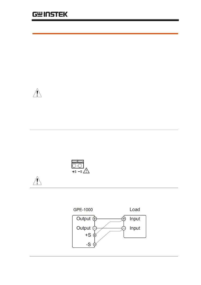
Single Load
1. Connect the +S terminal to the positive
potential of the load. Connect the -S terminal to
the negative potential of the load.
Bekijk gratis de handleiding van GW Instek GPE-1323, stel vragen en lees de antwoorden op veelvoorkomende problemen, of gebruik onze assistent om sneller informatie in de handleiding te vinden of uitleg te krijgen over specifieke functies.
Productinformatie
| Merk | GW Instek |
| Model | GPE-1323 |
| Categorie | Niet gecategoriseerd |
| Taal | Nederlands |
| Grootte | 4219 MB |


