Growatt MOD 3-10KTL3-XA handleiding
Handleiding
Je bekijkt pagina 16 van 28
6.9 Backup(optional)
Backup means that the inverter can output 230/400V, 50/60Hz voltage to the load when
there is no grid. The MOD-XA inverter has the Backup function. If you need to use this
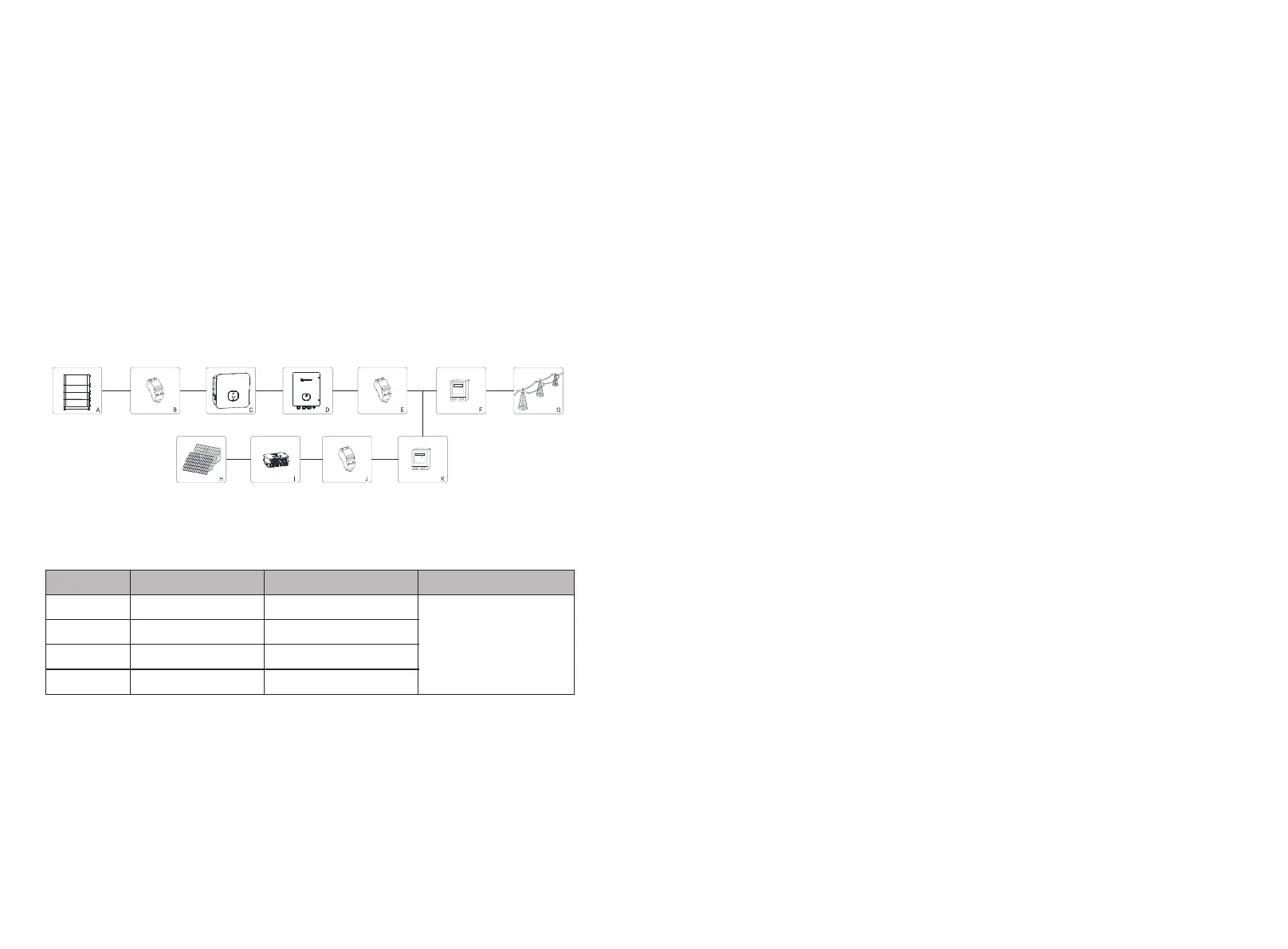
function, you need an additional Backup box. The system diagram is as the figure below.
Fig 6.14
6.8 GFCI(Standard)
This inverter includes an integrated residual current device .If the leakage current is
over 300mA and last for more than 300ms,the inverter will report 201 fault and the
OLED will display Residual I High.
The inverter has the function of detecting residual current and protecting the inverter
against residual current. If your inverter must equip a AC breaker which has the function
of detecting residual current ,you must choose a Type A RCD breaker with the rating
residual current more than 300mA.
Connection communication cable to the XA inverter
COM Port
XH Inverter COM
SYN 50-XH 30 COM
Control Board
RS 485 A
PIN17
PIN3
CN8
RS 485 B
PIN18
PIN4
BOX.EN+
PIN21
PIN5
BOX.EN-
PIN22
PIN6
As shown in Fig 6.14 above,a complete storage system includes PV panels( MOD XA
series inverter without PV panel), inverters, backup box, public grid and other
accessaries. In this system,the photovoltaic inverter is a key device. If the customer want
to enable the Backup mode, please refer to 9.3.3 Backup Mode Setting.
Note:
1.The max. power output at the off grid is 10kW when the battery power is enough.
2.The backup function is permitted to be commissioned only by professionals. The
backup function requires a backup box provided by Growatt.
Debugging 7
1.After connecting the battery (at least three ARK batteries) and turning on the
switch,the inverter display will show the following information:No AC connection
error,the inverter LED will turn red.
If other information is displayed,please refer to Chapter 13.If you encounter any
problems during the debugging process and cannot solve it,please contact customer
service.
2.Close the circuit breaker or switch between the inverter and the grid, the inverter
will start a countdown to the self-check,and after the self-check is normal,it will be
connected to the grid.
3.In normal operation,the leaves of the inverter indicator window will turn green.
4.Finish debugging.
Working Mode 8
8.1 Normal mode
In this mode, the inverter works normally.When the battery and the grid are connected
normally, the inverter counts down and connects to the grid, and the green light is on.
8.2 Failure mode
The inverter controls the chip monitors and adjusts the state of the system in real time.
When the inverter monitors any unexpected conditions,such as system failure and
inverter failure,the display will show the fault information.In the failure mode,the
inverter will indicate the leaves of the window will turn red and the inverter output will
be disconnected from the grid.
26
25
Bekijk gratis de handleiding van Growatt MOD 3-10KTL3-XA, stel vragen en lees de antwoorden op veelvoorkomende problemen, of gebruik onze assistent om sneller informatie in de handleiding te vinden of uitleg te krijgen over specifieke functies.
Productinformatie
| Merk | Growatt |
| Model | MOD 3-10KTL3-XA |
| Categorie | Niet gecategoriseerd |
| Taal | Nederlands |
| Grootte | 5306 MB |


