Gigabyte MX33-BS0 handleiding
Handleiding
Je bekijkt pagina 20 van 81
- 20 -
Hardware Installation
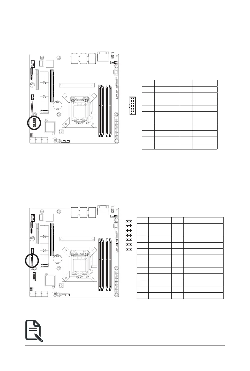
12) F_U32 (Front Panel USB 3.2 Connector)
TheheaderconformtoUSB3.2specication.EachUSBheadercanprovidetwoUSBportsviaanoptional
USB bracket. For purchasing the optional USB bracket, please contact the local dealer.
1110
201
Pin No. Denition Pin No. Denition
1 Power 11 IntA_P2_D+
2 IntA_P1_SSRX- 12 IntA_P2_D-
3 IntA_P1_SSRX+ 13 GND
4 GND 14 IntA_P2_SSTX+
5 IntA_P1_SSTX- 15 IntA_P2_SSTX-
6 IntA_P1_SSTX+ 16 GND
7 GND 17 IntA_P2_SSRX+
8 IntA_P1_D- 18 IntA_P2_SSRX-
9 IntA_P1_D+ 19 Power
10 NC 20 No Pin
13) FP_1 (Front Panel Header)
Connect the power switch, reset switch, speaker, chassis intrusion switch/sensor and system status indicator
on the chassis to this header according to the pin assignments below. Note the positive and negative pins
before connecting the cables.
The front panel design may differ by chassis. A front panel module mainly consists of power switch,
reset switch, power LED, hard drive activity LED, speaker etc. When connecting your chassis front
panel module to this header, make sure the wire assignments and the pin assignments are matched
correctly.
1
2423
2
Pin No. Denition Pin No. Denition
1 Power LED+ 2 5V Standby
3 No Pin 4 ID LED+
5 Power LED- 6 ID LED-
7 HDD LED+ 8 System Status LED (Green)
9 HDD LED- 10 System Status LED (Yellow)
11 Power Button 12 LAN1 Active LED+
13 GND 14 LAN1 Link LED-
15 Reset Button 16 SMBus Data
17 GND 18 SMBus Clock
19 ID Button 20 Case Open
21 GND 22 LAN2 Actve LED+
23 NMI Switch 24 LAN2 Link LED-
Bekijk gratis de handleiding van Gigabyte MX33-BS0, stel vragen en lees de antwoorden op veelvoorkomende problemen, of gebruik onze assistent om sneller informatie in de handleiding te vinden of uitleg te krijgen over specifieke functies.
Productinformatie
| Merk | Gigabyte |
| Model | MX33-BS0 |
| Categorie | Niet gecategoriseerd |
| Taal | Nederlands |
| Grootte | 9403 MB |


